


 881 / 1526

25
ENGINE2.2LDICOR
Fig. 47
Fig. 48
l
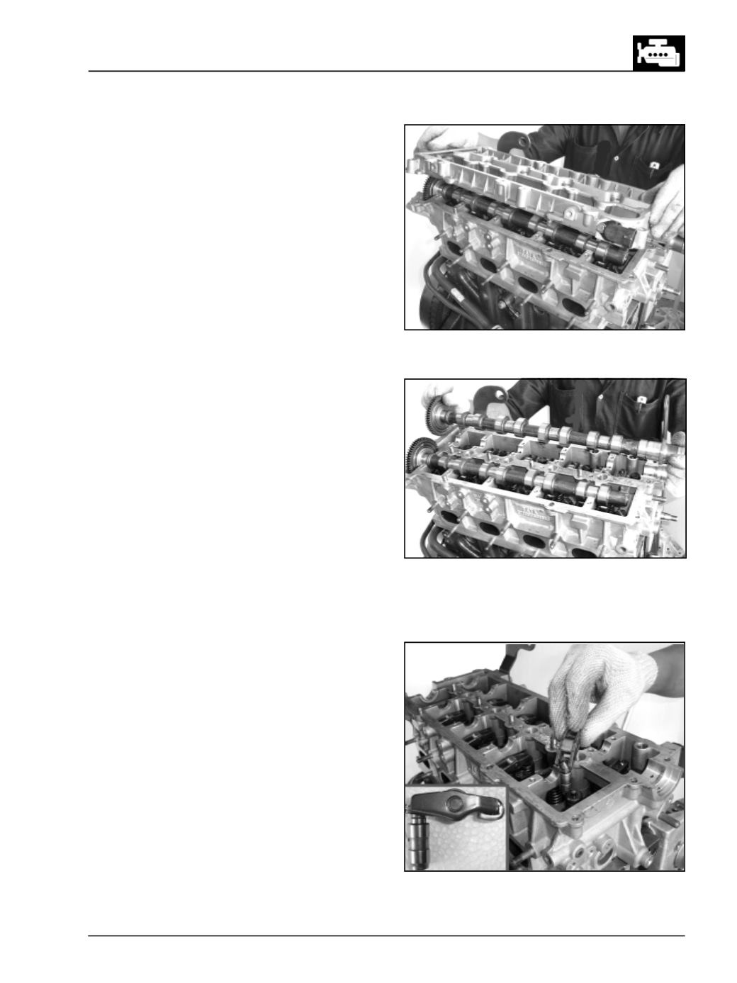
Remove the Intake &Exhaust camshafts. (Fig. 47)
l
Take out the Roller finger followers & hydraulic lash
adjuster assembly by lifting upwards. (Fig. 48)
Note : The Roller finger followers & hydraulic lash
adjusters can also be removed after taking out the
cylinder head from cylinder block.
Fig. 46