


 884 / 1526

28
ENGINE2.2LDICOR
DisassemblyAndAssemblyofCylinderHeadSubAssemblies
l
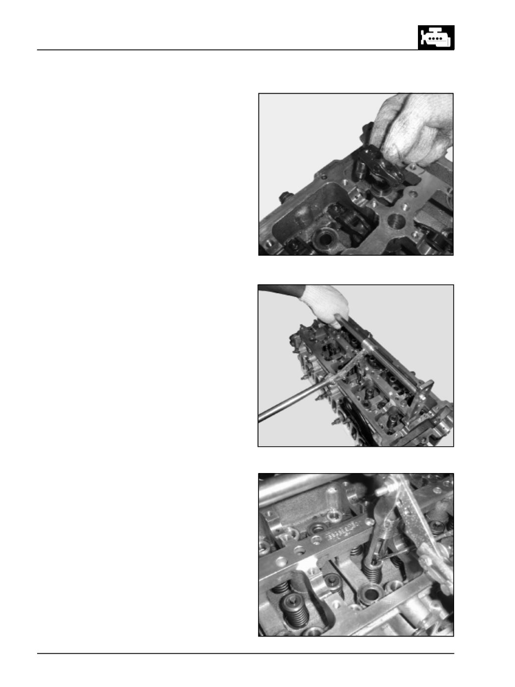
Fit the valve spring compressor, compress valve
springs and remove lock halves. (Fig. 54 & 55)
Fig. 53
Fig. 54
Fig. 55
l
Remove all the roller finger followers (RFF) along
with hydraulic lash adjusters (HLA) by lifting
vertically and place them in correct sequence and
in vertical direction only to avoid oil drain from
HLA. (Fig. 53)