


 346 / 1526

14
SUSPENSION
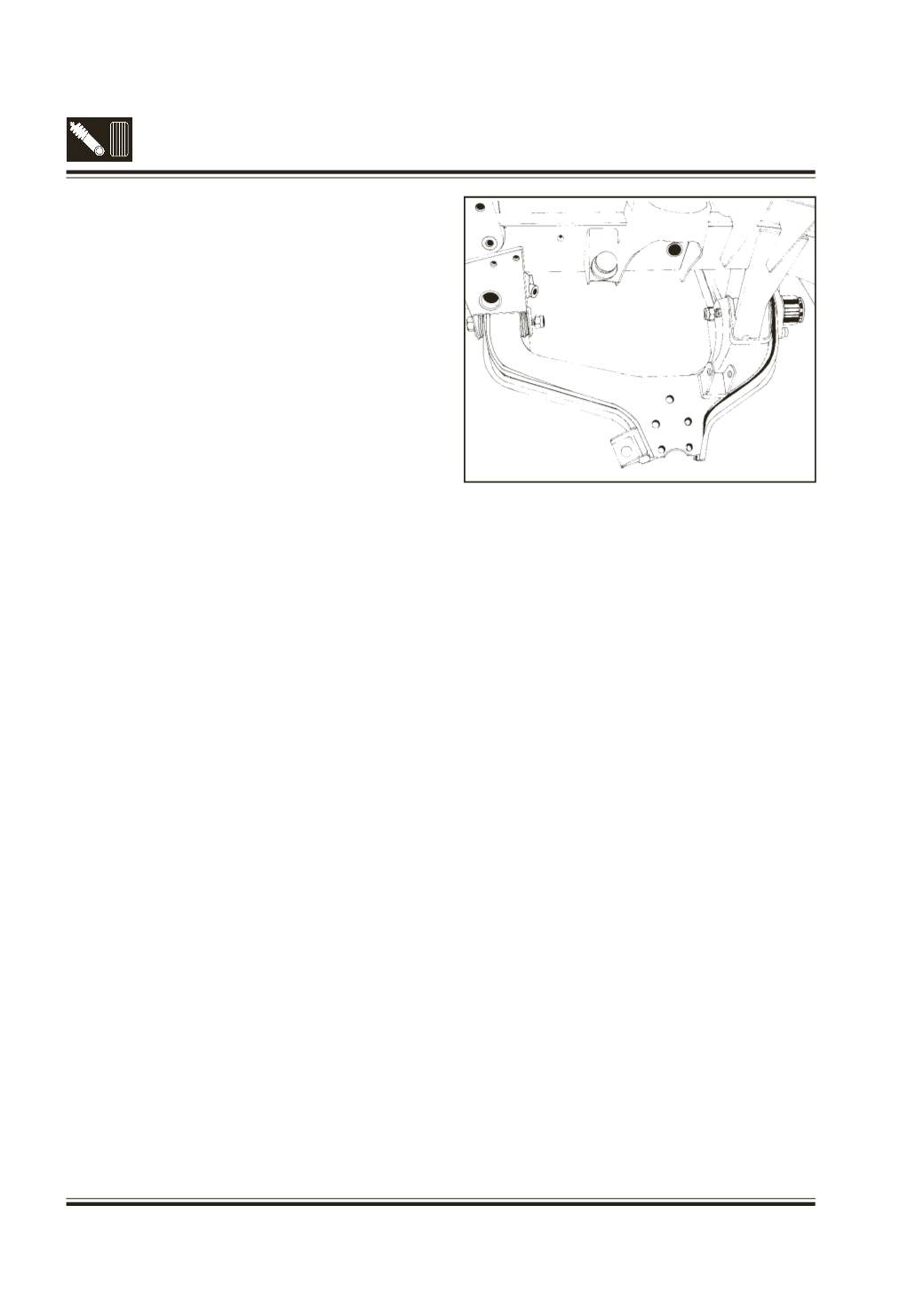
4F. REMOVAL/DISMANTLING OF LOWER
WISHBONE
(Fig. 8)
l
Unscrew and remove 2 screws holding bracket
(torsion bar mounting) to lower wishbone. Take
out the bracket.
l
Take out the split pin locking the castle nut of
stub axle bottom ball joint. Properly support the
stub axle. Push out the ball joint from stub axle.
l
Unscrew and remove two nyloc nuts of pivot pins
holding lower wishbone with mounting brackets
on frame, using adaptor
(Pt.No. 2699 5890 41
01). Push out pivot pins and remove lower
wishbone (Fig.11)
l
Unscrew and remove 4 screws holding the ball
joint to lower wishbone. Take out the ball joint.
l
Pry out pivot bushes from lower wishbones, if
necessary.
l
Pry out pivot bushes from lower wishbone
mounting bracket, if necessary.
5. INSPECTION OF PARTS
l
Check the condition of the following for wear,
damage. If necessary replace with new ones.
l
Check the condition of antiroll bar for bend, cut,
damage etc. Replace it with new one, if
necessary.
l
Check the condition of rubber links and bushes
of antiroll bar. If necessary replace with new ones.
l
Check the condition of pivot bushes, washer and
spindle of upper wishbone assembly If necessary
replace with new ones.
l
Check the condition of ball joints of upper
wishbone and lower wishbone. Check for
excessive play in ball joints. If necessary replace
with new ones.
l
Check the condition of rubber boots of top and
bottom ball joints. If it is damaged, replace the
ball joint.
l
Check the condition of shock absorber for leakage
etc. Check the condition of rubber bushes, washer
etc. If necessary replace with new OE shock
absorber
l
Check the condition of torsion bar for wear cuts
etc. If necessary replace with new one.
l
Check the condition of bump and rebound stopper.
If found worn/damaged replace with new ones.
Fig.14 Lower wishbone assembly
l
Check the condition of upper wishbone and lower
wishbone. If found necessary replace with new
ones.
6. ASSEMBLY / INSTALLATION PROCEDURE
6A. ASSEMBLY / INSTALLATION OF LOWER
WISHBONE
l
Assemble lower ball joint on stub axle for 4 x 4
version & then on the lower wishbone.
l
If 2 halves of pivot bushes removed earlier from
lower wishbone, fit each half from either sides,
using suitable drift.
l
Locate lower ball joint on the lower wishbone &
install 2 hex bolt (M12), washer, spring washer,
hex nut and then 2 hex screws (M10), washer,
spring washer, hex nut.Tighten M 12 bolts to 9.7
mkg torque and M10 screws to 6.5 mkg. torque.
l
Fit bracket (torsion bar mounting) on the lower
wishbone with 2 hex screws and washers and
tighten hex screws to 9.7 mkg. torque.
l
If 2 halves of pivot bushes removed earlier from
mounting bracket of lower wishbone, fit each half
from either sides, using suitable drift.
l
Position the lower wishbone on chassis frame.
Align pivot bushes and holes on bracket using
suitable punch.
l
Insert the shims to fill the gap at front pivot, Install
pivot pins (serrated pin in the torsion bar mounting
bracket) and nyloc nuts. Tighten nyloc nuts to
14-16 mkg torque, using adaptor (Pt. No. 2699
5890 41 01) with torque wrench.