


 348 / 1526

16
SUSPENSION
6B. ASSEMBLY/INSTALLATION OF UPPER
WISHBONE
l
If the pivot bushes and spindle were removed
earlier, press new pivot bush on the upper
wishbone using suitable drift.
l
Insert spindle into the upper wishbone and then
press the other pivot bush.
l
Fit the washers, spring washers and the two M12
screws connecting spindle and upper wishbone.
Maintain angle 22
0
& height 30 mm from the flat
surface of wishbone as shown in Fig.15. Tighten
screws to 8-9 mkg. torque.
l
Check the condition of rubber boot of top ball
joint. If it is damaged replace the ball joint. If there
is undue free play in ball joint, replace the ball
joint assembly.
l
Fit the top ball joint assembly on the upper
wishbone and tighten the 4 screws, with spring
washers, use anaerobic compound and tighten
to specified torque.
l
Position the upper wishbone assembly on the
chassis frame, insert the shims removed earlier,
tighten the 2 screws connecting the spindle of
upper wishbone to the bracket on chassis frame
(Fig.16).
l
Install stub axle (Refer front axle Group).
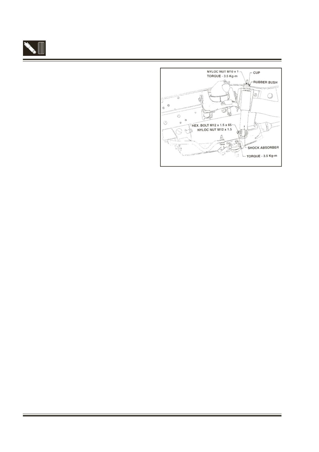
6C. INSTALLATION OF FRONT SHOCK
ABSORBER
(Fig.17)
l
Install washer, spacer tube and rubber bush on
to top mounting bolt of shock absorber.
l
Position the shock absorber properly between top
mounting bracket on frame and bottommounting
bracket on lower wishbone.
l
Install the hex bolt in bottom mounting bracket
and tighten nyloc nut to 8.3 mkg. torque.
l
Install rubber bush, washer and nyloc nut on
shock absorber top mounting bolt and tighten
nyloc nut to 3.5 mkg. torque.
l
Take out jack.
Fig. 17 - Installation of shock absorber