


 350 / 1526

18
SUSPENSION
6D. INSTALLATION OF FRONT ANTIROLL BAR
(Ref. Fig.18)
l
Position the anti roll bar between the brackets on
lower wishbone.
l
Install cup, rubber bush & washer on antiroll bar
mounting bolt. Insert mounting bolt in mounting
bracket on lower wishbone. Install cups, rubber
bushes, sleeve, antiroll bar & nyloc nut on
mounting bolt properly. Tighten nyloc nut such
that bolt end should project 10 to 12 mm above
nyloc nut.
l
Apply silicon grease molykote 33 (medium) on
antiroll bar over bearing width of bearing block to
be mounted on chassis frame. Fit bearing block
and mounting clamp with hex. screw, spring
washer and bright washer.
l
Tighten bearing block clamp mounting screws to
4.9 mkg. torque.
l
Ensure equal gap between wishbone and antiroll
bar on both sides.
6E. INSTALLATION OF FRONTWHEELS
l
Install the front wheels on the hub assembly and
tighten the wheel nuts by hand.
l
Remove the supports, supporting the chassis
long member.
l
Tighten the wheel nuts to a torque of 12-15 mkg.
Note
Hold the steering wheel and tighten the castle
nuts of stub axle top mounting ball joint and stub
axle bottom mounting ball joint to 12-15 mkg.
torque. Lock the castle nuts with split pins.
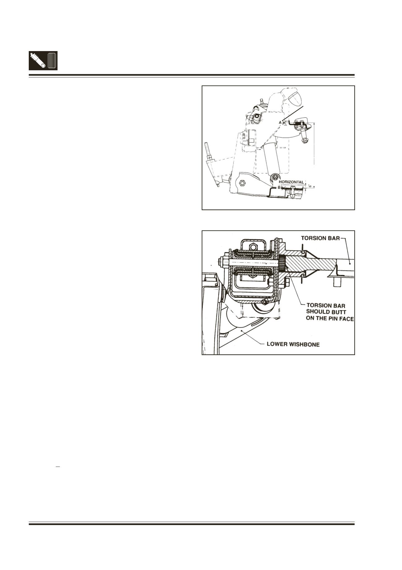
6F. INSTALLATIONOF TORSION BAR
(Fig.19)
l
Assemble wheels, if removed earlier.
l
Jack up chassis from behind front wheels from
(RH & LH) side and adjust the chassis height to
(Top of chassis at the front Location hole)
550 + 3 mm. (Alternatively adjust the distance
between upper wishbone mounting bracket and
lower wishbone to approx. 295 mm or angle of
lower wishbone to approx. 6
0
as shown in the
fig.20)
Fig. 20 - Lower wishbone height adjustment
Fig. 21 - Installation of torsion bar
l
Apply a light coat of ‘Servo Molex grease 3%
MoS2' to the splines of the torsion bar.
l
‘R’ and ‘L’ are marked at one end of RH and LH
torsion bars respectively. Install unmarked end
of torsion bar RH to the bracket on lower
wishbone of RH side. Similarly install torsion bar
LH. (Fig. 21)
l
Assemble the levers on the torsion bar at rear
end, such that after putting one nut, 1 to 3 mm
protrusion of the anchoring bolt is maintained
for Safari 4x4 and 4x2.
UPPERWISHBONE
MOUNTING BRACKET
LOWERWISHBONE
MOUNTING BRACKET