


 280 / 1526

39
GEAR BOX G-76
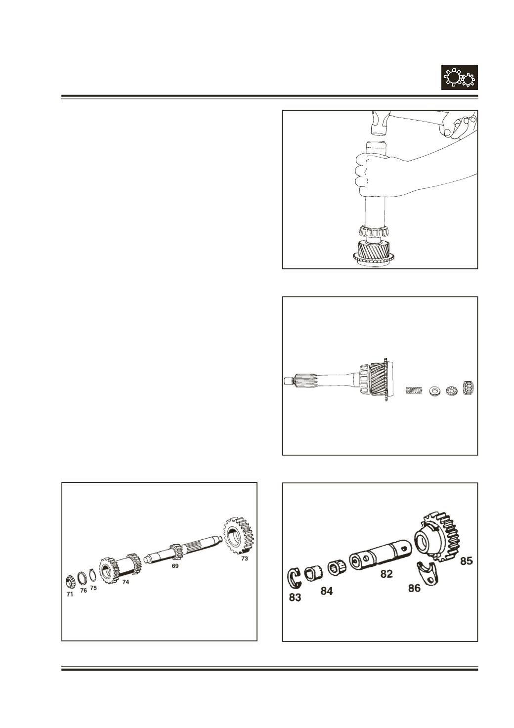
SUB ASSEMBLY OF COUNTER SHAFT
Refer fig. 69
Heat the constant mesh 3rd/4th gear (74) to 100-
120 deg.C and press over counter shaft (69) with
proper support in such a way that bigger gear i.e. 4th
is facing upward. Fit circlip (75).
In the same way fit 5th gear (73) over other side such
that longer boss is facing upwards. Ensure proper
abutment of gear on the counter shaft.
Press inner race of taper roller bearing (71) over
counter shaft 5th gear side end with help of drift,
Pt.No.2654 5890 26 06 and handle
Pt.No.2640 5890
35 11. Place outer race over it.
Reverse the assembly, slide spacer (76) and press
another taper roller bearing inner race (71a). Place
outer race over it.
SUB ASSEMBLY OF DRIVE SHAFT
Press inner race of taper roller bearing (11) with the
help of drift
Pt.No. 2654 5890 26 05.
Fig. 70
Fit compression spring (4), spacer (5) of required
thickness, thrust bearing (6) and roller cage (7) in
drive shaft bore.
Fig. 71
Select spacer thickness as per procedure given.
SUB ASSEMBLY OF REVERSE IDLER GEAR
SHAFT
Refer fig. 72
Fit snap ring (83a) over R.I. gear shaft (82).
Slide roller ring (84) along with R.I. gear (85) over
shaft. Fit another snap ring (83).
Fig. 72
Fig. 71
Fig. 70
Fig. 69