


 278 / 1526

37
GEAR BOX G-76
Hold the main shaft vertically in coupling flange with
up side down.
Slide the 1st gear sub-assembly (35) along with the
needle roller cage (36) and engaging gear 1st/2nd
(32) over main shaft such that engaging gear is
upwards.
Fig. 61
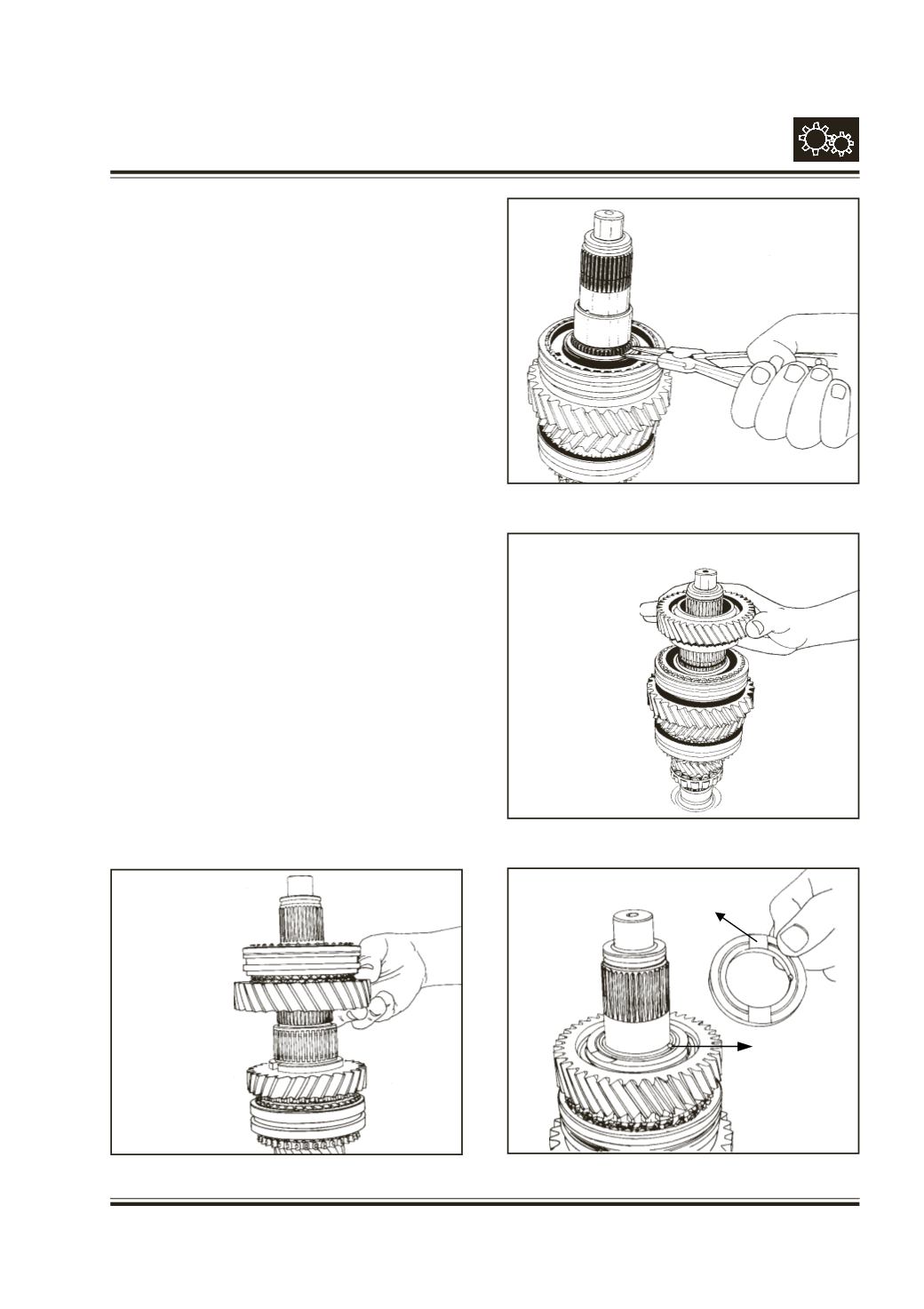
Select suitable snap ring (31) and fit it over main shaft
groove. Snap rings are available in the thickness
ranging from 1.7 to 2 mm in the step of 0.05 mm.
Fig. 62
Slide the 2nd gear sub-assembly (29) over main shaft
along with the needle roller cage (24a) and synchro
cone (30) such that synchro cone facing downwards.
Fig. 63
Locate 3 mm Dia. locking ball (26) at seat on main
shaft with help of grease. Slide spacer (27), aligning
notch with the locking ball. Ensure that oil pocket over
the spacer is facing upwards i.e. towards 3rd gear.
Fig. 64
Fig. 64
Fig. 63
Fig. 62
Fig. 61
oil pocket
locking ball
(spacer)