


 183 / 1526

38
486 PL ENGINE
P
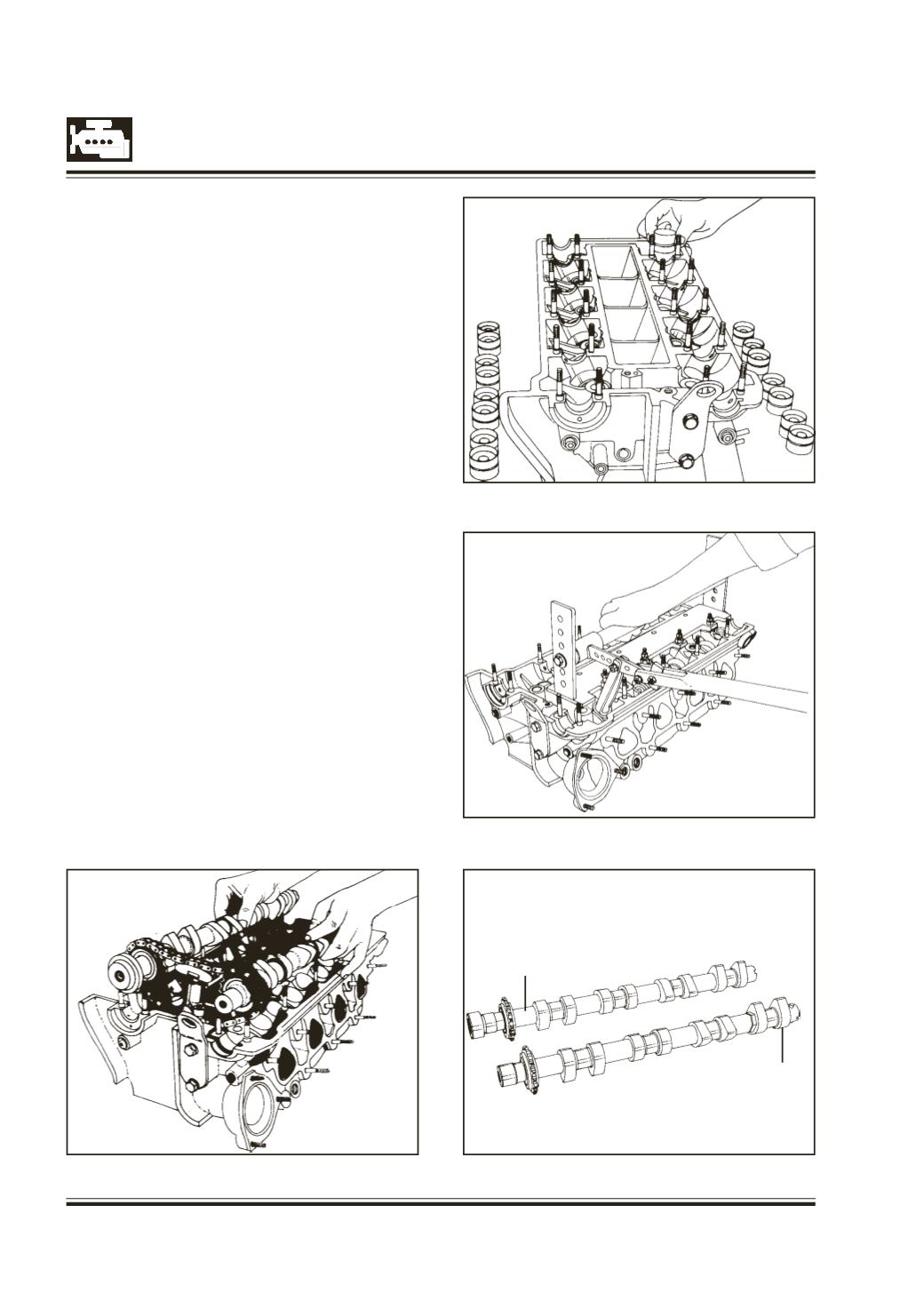
Fig. 81
Fig. 80
Fig. 79
Fig. 78
Remove the cam shafts along with oil seal, chain &
chain tensioner. Fig. 78
Separate out oil seal.
Remove all hydraulic tappets. Fig. 79
Support cylinder head and mount special tool,
(Pt No. 2699 5890 0603) valve spring compressor
on cam shaft bearing cap studs.
Compress valve springs and remove valve lock half
Fig. 80
Remove valve spring retainer & valve springs.
Take out valves from the bottom of cylinder head.
Remove oil seal from valve guide. If observed to be
damaged.
Note : Valve guide seals not to be reused once it is
removed.
Place the valves in the correct sequence on a
suitable stand.
Pull out the chain sprocket on the cam shaft with
puller Pt. No. 2654 5890 0305.
(The cam with the bigger boss is the exhaust cam
shaft) Fig. 81
INTAKE CAMSHAFT
EXH. CAM SHAFT