


 772 / 1002

ELECTRICAL
151
1.2 TURN TIP – LANE CHANGER.
1.2.1 Description
The turn-tip feature allows the driver to activate the turn signal lights by momentarily pressing the turn switch
input up or down. The turn signal lights flash for a predefined number of times.
1.2.2 Conditional Requirements
Activation –
• Respective turn indicator stalk switch is gently pushed and released
Tell-tale Indication -
On IC as long as the turn indicators are operated.
On Fault –
In case of partial bulb out, BCM flashes other bulbs with double frequency and logs respective DTC.
1.2.3 Operating Voltage Range
DESCRIPTION REQUIREMENT
VOLTAGE
Turn Tip – Lane
Changer
.
Normal operating voltage
12V
Min & Max operating voltage range
9V-16V
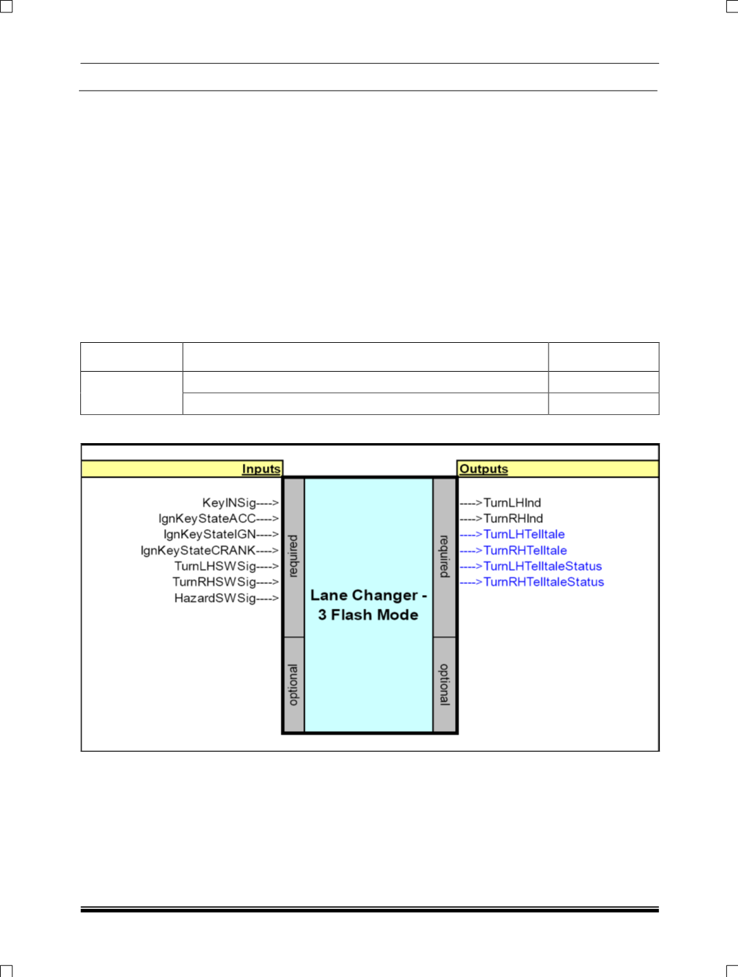
1.2.4 Inputs & Outputs