


 107 / 310

ENGINE
.
61
7. Check for leakages through valve seat by pour-
ing gasoline on valve head. Gasoline must not
seep past valve seat.
E VALVE SEAT INSERTS:
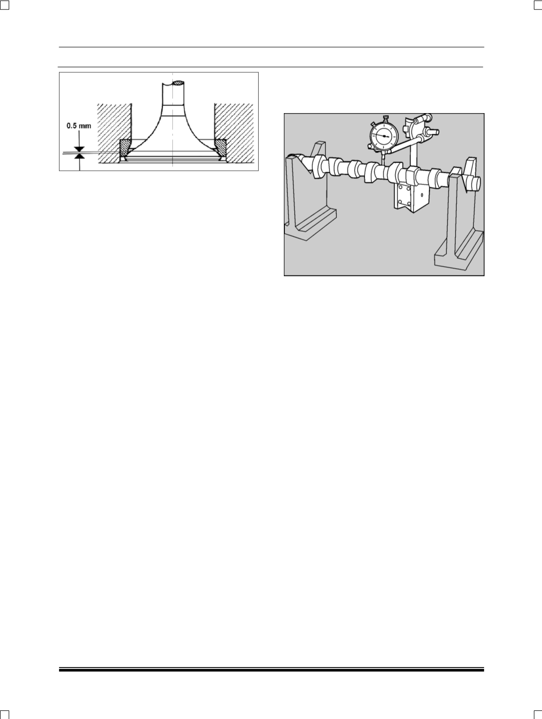
1. For removing valve seat inserts from cylinder
head use suitable boring machine. Bore old in-
sert thin
(About 0.5 mm thickness)
and then pry
it out.
2. Alternatively use a suitable turning tool to cut an
annular groove into valve seat insert and then
pull it out with a suitable puller. In order to avoid
damaging machined cylinder head mating sur-
face with crank case, place any soft protective
sheet metal under supports of puller.
3. Measure valve seat insert bore diameter in cyl-
inder head.
4. If boring and prying is done carefully without
damaging valve seat insert bore in cylinder
head, fitment of an over size valve seat insert
will not be necessary.
5. Re-machined valve seat insert bore in cylinder
head must be exactly at right angle to cylinder
head mating surface with crank case.
6. All specified dimensions should be strictly main-
tained to ensure proper interference of valve
seat insert in its bore.
7. Clean valve seat insert and its bore in cylinder
head thoroughly.
F JUST BEFORE INSTALLATION:
1. Place valve seat insert in mixture of Methanol
and dry ice for about 20-30 minutes to bring
temperature down to -150ºC.
2. Heat cylinder head to approximately 80ºC in hot
water bath.
3. Install valve seat insert in cylinder head bore
quickly by light hammering
4. Machine valve seat in cylinder head.
G CAM SHAFT INSPECTION
1. Check cam shaft run out at 2nd journal by sup-
porting it on V-block at 1st and 3
rd
journal.
2. Check cam shaft journal dimensions. Record the
readings.
3. Carry out visual inspection of cam shaft for:
•
Overheating of journals, this is indicated by
bluish/ brown colour.
•
Deep scoring marks on journals and cam
lobes
•
Cracks, which should be checked on a mag-
netic crack detector.
4. Check hardness of cam shaft journals and cam
lobes, it should be 47 HRC.