


 699 / 1235

ANTI LOCK BRAKING SYSTEM (ABS)
7
ANTI-LOCK
BRAKING
SYSTEM (ABS)
B. BRAKING WITH EBD IN OPERATION
In case of a braking where the ABS ECU detects a
slip difference between the front and rear wheels,
EBD comes into operation. If the difference in wheel
slip between the front and rear wheels exceeds a
predetermined threshold the ABS activates the
pressure inlet valves for the rear wheels, closing the
valves and preventing further pressure build up at
that rear wheels.
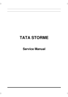
If during the braking event, this slip ratio between the
front and rear axle reduces below the threshold level
the inlet valves will be de-activated and switch back
to their normally open state allowing further pressure
increase at the rear axle. In this way the rear axle
can follow more closely to the Ideal braking force
distribution curve for the rear axle
(See Figure a).
If the driver reduces the brake pedal effort during
EBD control, brake fluid can return to the TMC
through the one way valve located within the
modulator in parallel to the Inlet valve.
If the driver releases the brake, the inlet valves will
be deactivated and fluid can return to the TMC via
the inlet valve and the one way valve.
EBD control only acts upon the rear axle and can
only limit pressure being applied to a wheel, it cannot
perform pressure reductions.
Figure a: Pressure increase on rear axle
following ideal brake force distribution curve.
C. BRAKING WITH ABS IN OPERATION
In case of braking where the ABS ECU detects a
significant difference in the wheel speed information
from an individual wheel. The electronic control unit
instructs the hydraulic modulator to vary the brake
pressure being applied at the affected wheel(s).
There are three stages to this control.
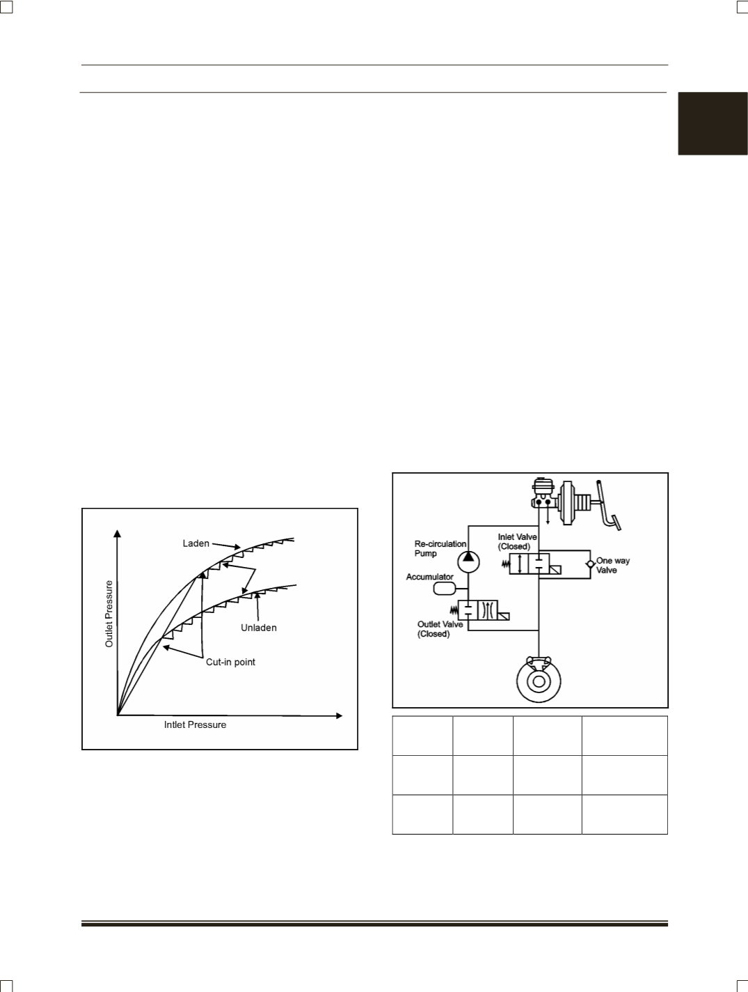
1. PRESSURE MAINTAINING
(HOLD)
PHASE
When the braking forces being applied are higher
than the forces that can be transmitted to the road
surface for a specific wheel, the ECU will detect that
the wheel is tending towards lock (
Slip relative to
other wheels and a calculated vehicle reference
speed)
. It will then activates the relevant inlet valve
within the hydraulic modulator, switching it from its
normally open position to closed, hence preventing
further pressure being transmitted from the TMC to
the affected wheel brake. As the outlet valve is
closed in this phase the pressure at the wheel is
maintained.
If the driver reduces the brake pedal effort during
ABS control, brake fluid can return to the TMC
through the one way valve located within the
modulator in parallel to the Inlet valve.
Solenoid
valve
Electricity
status
Valve
open-close
Open-close
channel
INLET
ON
CLOSE Master cylinder
-Wheel cylinder
OUTLET OFF
CLOSE Wheel cylinder
-reservoir