


 705 / 1235

ANTI LOCK BRAKING SYSTEM (ABS)
13
ANTI-LOCK
BRAKING
SYSTEM (ABS)
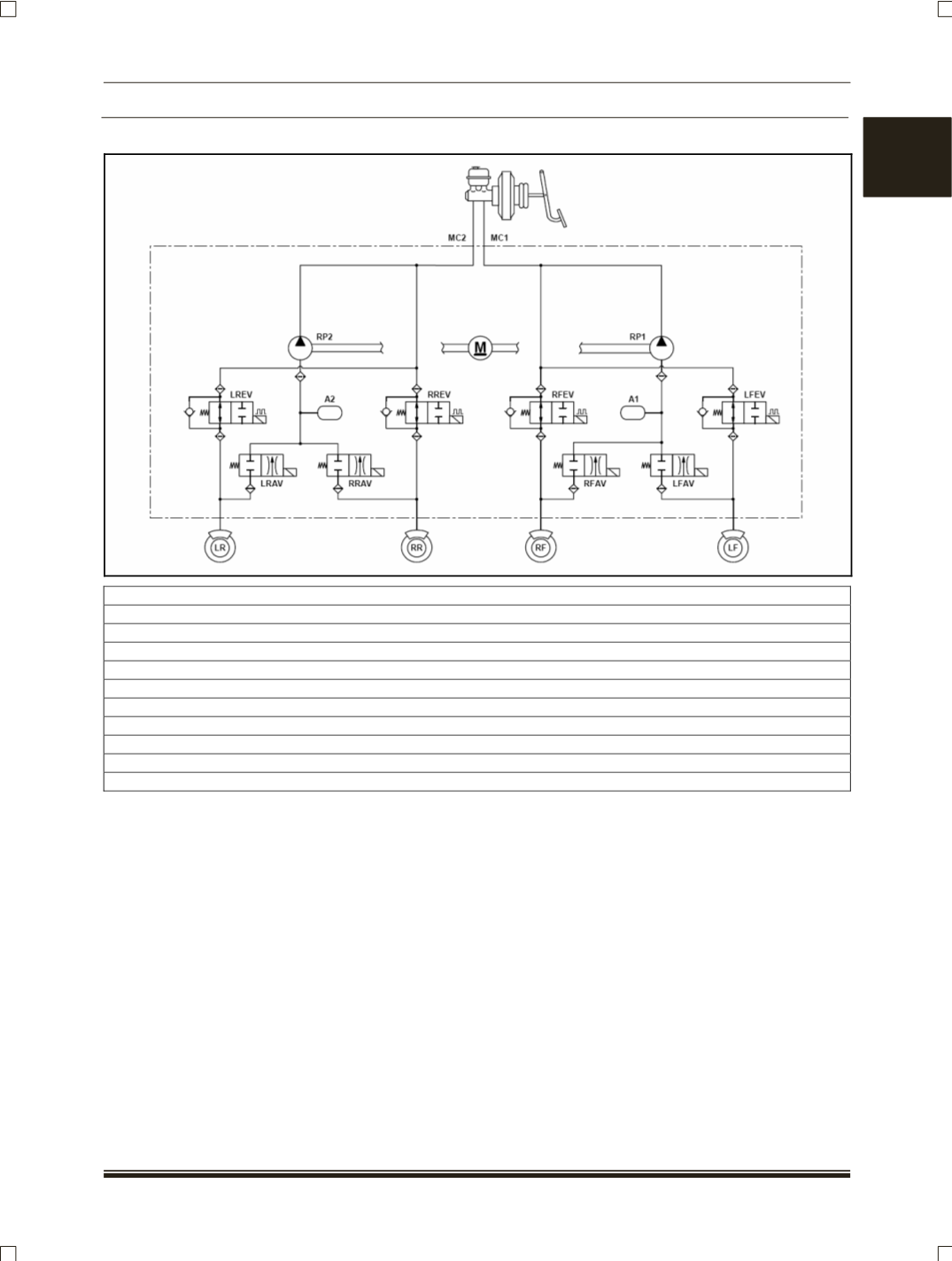
(ii) HYDRAULIC CONTROL UNIT (HCU)/HYDRAULIC MODULATOR
RF
: Front right
LR
: Rear Left
RR
: Rear Right
LF
: Front Left
MC1
and
MC2
: Primary and Secondary brake circuits
RREV
and
RRAV
: Inlet and Outlet solenoid valves of rear right wheel
LFEV
and
LFAV
: Inlet and Outlet solenoid valves of front left wheel
LREV
and
LRAV
: Inlet and Outlet solenoid valves of rear left wheel
A1
and
A2
: Accumulators of the circuits MC1 and MC2 respectively
RP1
and
RP2
: Recirculating pump of the circuits MC1 and MC2 respectively
M:
Motor for driving Recirculating pumps
It consists of a Return Pumps, Solenoid Valves,
Damping Chamber, Accumulator, Non-Return Valve
and Motor. It forms the link between the TMC and
the foundation brakes. It implements the commands
issued by the ECU by using solenoid valves to
control the pressure at the foundation brakes.
There are four pairs
(4-channel system)
of Inlet and
Outlet valves located in the modulator. Solenoid
valves are responsible for modulating the pressure in
the wheel brake during active ABS control.
The Return Pump element is installed in the center
of the modulator and is driven by an electric Motor.
The pump transfers the brake fluid emerging from
the wheel brakes through the accumulator on its way
back to the TMC The pump and valve actuation can
be felt on the foot pedal as pulsations. In order to
prevent damage to the TMC primary seals from the
compensating port, the design of TMC is changed to
central valve type
(CV/CV).
The accumulator absorbs the surge in brake fluid
that accompanies the pressure reduction phase. The
Damping Chamber suppresses pressure oscillations
within the hydraulic system, preventing them from
being propagated back to the brake pedal and
reduces noise levels in the system