


 587 / 1428

STEERING SYSTEM
575
STEERING
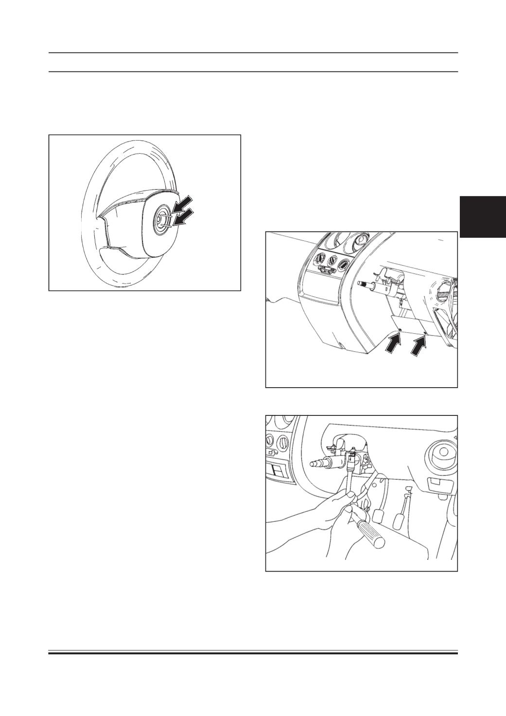
CAUTION :
Care should be taken such that self cancellation lugs
do not get damaged (self cancellation lugs are shown
in below figure with arrows)
Inspection :
1. Check for any damage to self cancellation lugs, if
found, replace complete steering wheel.
Installation :
1. Align the marks made on the steering wheel and
the shaft. Install steering wheel on steering shaft.
2. Tighten the steering wheel nut to the specified
torque.
TIGHTENINGTORQUE FORSTEERINGWHEEL
NUT = 8.6 ± 0.2 Kg-m
3. Fit horn pad (Press fit type)
4. Connect battery.
STEERING COLUMN ASSEMBLY
Removal :
1. Disconnect battery.
2. Remove steering wheel (Refer steering wheel
removal procedure)
3. Remove combi switch assembly. (Refer combi
switch assembly removal / Body Electrical group)
4. Remove ignition switch assembly. (Refer ignition
switch assembly removal procedure/ Body
Electrical group)
5. Remove two screws of nacelle bottomcover.
6. Remove four nuts of steering column assembly.