


 274 / 1428

268
ENGINE 273 MPFI
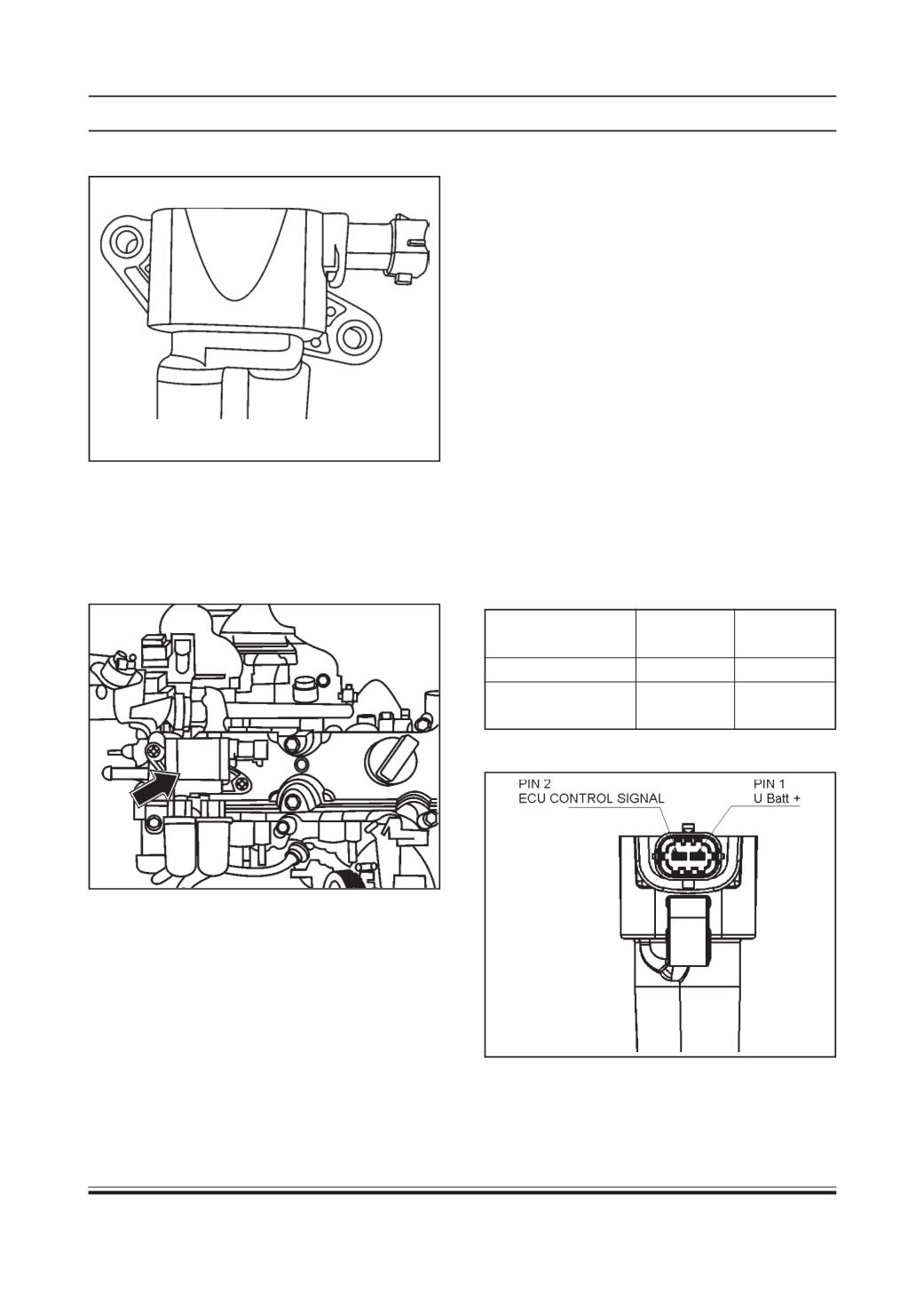
IGNITION COIL
Installation Method
The coil is mounted at the engine on top of the cylinder
head cover. The connection between high voltage
terminal is made by suitable ignition cables.Adefective
cable could cause damage to the coil.
Storage and Operating Condition
The following temperatures must not be exceeded.
Ambient temp. range: - 40°C to 110°C
Storage temp.: - 40°C to 130°C
During storage the coil must not be exposed to a wet
and dusty environment.
Max life Time: 10 Years.
Stand alone diagnosis
Winding Resistance (At room Temperature)
Primary Winding Resistance: 370-430 ohm
Measure between pin 1&2 (Primary)
Secondary Winding Resistance: 5200-6200 ohm
Measure between high voltage terminals (Secondary).
Pin Details
Signal
Connector ECU
Pin No.
Pin No.
UBKL.15
1
-
Ignition Coil
(ECU Control Signal) 2
55
Pin Configuration
Type
ZS-K1X2
Location
The ignition coil assembly is mounted on engine at
the top of cylinder head cover .
Working Principle
The ignition coil operates according to the laws of
induction. The unit consist of twomagnetically coupled
copper coils (primary and secondary windings). Energy
is stored in the primary winding’s magnetic field by
allowing a current to flow through the primary circuit
switched by the power stage.
At the firing point current flow is interrupted which
induces secondary voltage in the coil’s secondary
winding.
The ignition coil has two high voltage terminal one for
waste spark and the other for the ignition spark.