


 270 / 1428

264
ENGINE 273 MPFI
Stand Alone Diagnosis
Refer 3.11.5 Trouble Shooting and Diagnosis.
•
Use Multimeter
•
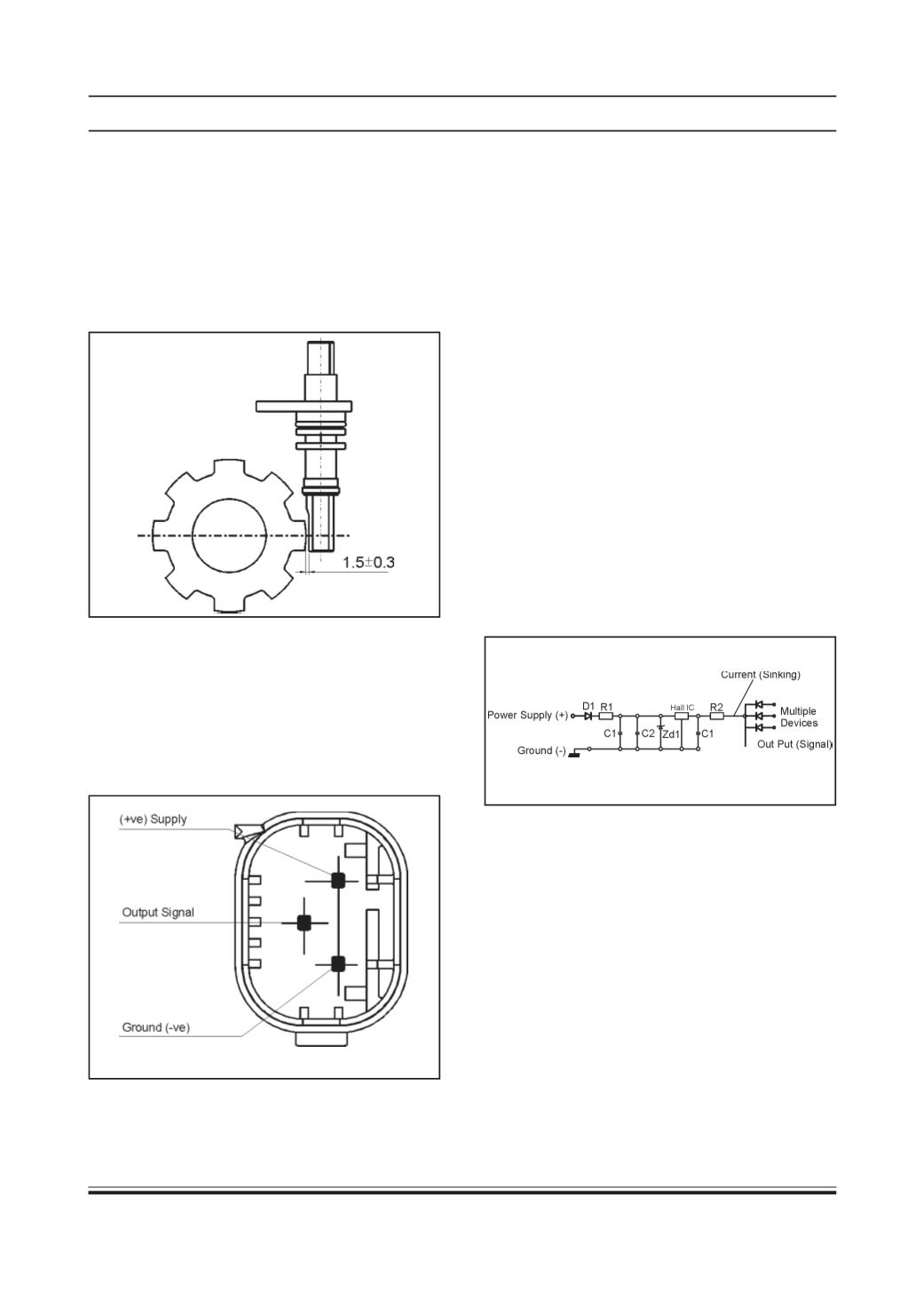
Pin Assignment
1 : Supply
2 : Ground
3 : Output to Cluster
•
Arrange a setup as per schematic wiring diagram
•
With ignition ON, Pulse volt in ON condition = 12
Volt DC
•
Measure pulse volt across ECU pin no. 6 and car
body as ground with Wiring harness connected to
ECU.
•
Rotate the wheel. Check output pulses.
SystemDiagnosis
•
Use TATADiagnostic Tool.
•
Check for Vehicle Speed Sensor value during driv-
ing.
Internal Circuit
On vehicle Removal & Refitment Procedure
Removal from vehicle :
•
Remove electrical connector of vehicle speed
sensor.
•
Unscrew the vehicle speed sensor.
•
Take out the sensor.
Refitment of Vehicle Speed Sensor on vehicle
•
Tighten the vehicle speed sensor.
•
Connect electrical connector of vehicle speed
sensor.
Specification : 8 pulses per revolution.
Operating voltage : 8 V to 18 V DC
Operating Current, No Load, & 12 V Supply : 15 mA
MAX.
Operating Frequency (Calculated at 750 RPM) : 100
Hz
Installation Guidelines
Storage Condition
Operating Temperature : -30°C to 125°C
Storage Temperature : - 40°C to 150°C
The components should be free from flash &moulding
defects.
Pin Assignment
mm