


 266 / 1428

260
ENGINE 273 MPFI
•
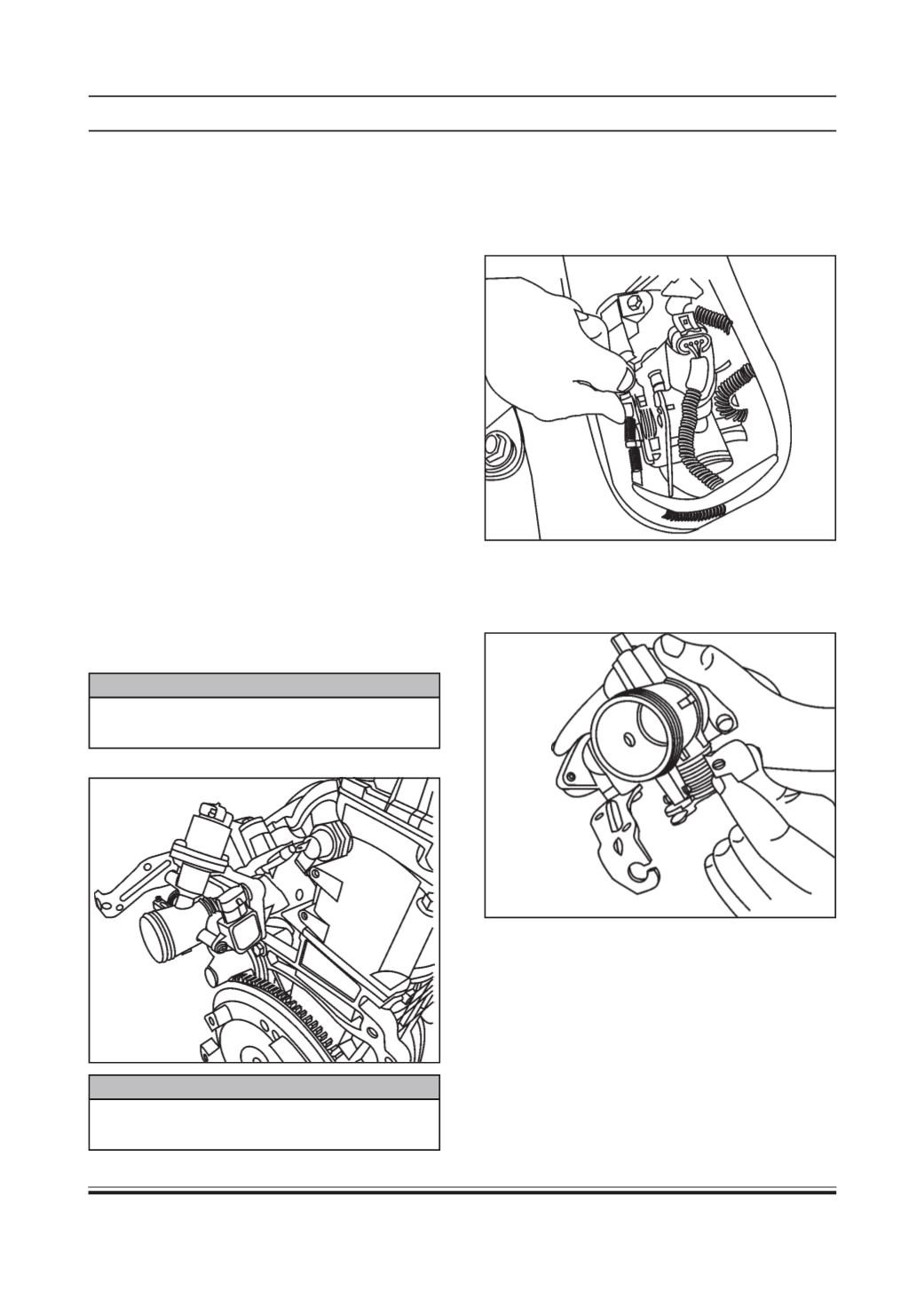
Remove the accelerator cable connection to throttle
body.
•
Remove the throttle body assembly by removing
the clamp using screw driver.
Inspection
•
Check for external damage of the body.
•
Check for free movement of the throttle lever.
PRECAUTION
Press the lock and pull out the coupler. Do not pull
the wire.
Stand Alone Diagnosis
Refer 3.11.5 Trouble Shooting and Diagnosis.
SystemDiagnosis
•
Use Tata Diagnostic Tool.
•
Check for throttle sensor voltage by pressing the
accelerator pedal in and out.
•
Measure resistance between pin no. 2 & 3
Permissible value = 2000 +/- 400 Ohm constant
throughout the movement of TPS.
•
Also check nominal O/P voltage ratio from stop to
stop. It should be 0.05 less than or equal to Ua/Uv
less than equal to 0.95.
Where,
Ua = Output voltage
Uv = Supply voltage
On vehicle Removal, Inspection & Refitment
Procedure :
Throttle Body assembly consists of -
1. Bare throttle body (with spring)
2. Throttle position sensor (TPS) and
3. IntakeAir Control valve (IACV) / ISC Valve
Removal Procedure for TPS
•
Remove battery negative terminal .
PRECAUTION
Ensure that the removed terminal is away from the
battery negative post/body.
•
Remove the Throttle body sensor connector.