


 169 / 1904

ENGINE 273 MPFI
163
ENGINE
GENERAL DESCRIPTION
The primary job of the cooling system is to maintain
the ideal engine working temperature and avoid over-
heating.
The engine performs best at specific designated
temperature. When the engine is cold, components
wear out faster, and the engine is less efficient and
emits more pollution. So another important job of the
cooling system is to allow the engine to heat up as
quickly as possible, and then to keep the engine at a
ideal constant working temperature.
Inside a engine, fuel is constantly burning. A lot of the
heat from this combustion goes right out the exhaust
system, but some of it soaks into the engine, heating
it up. The engine runs best when its coolant is about
200º F (93º C). At this temperature:
•
The combustion chamber is hot enough to
completely vaporize the fuel, providing better
combustion and reducing emissions.
•
The oil used to lubricate the engine has a lower
viscosity (it is thinner), so the engine parts move
more freely and the engine wastes less power
moving its own components around.
•
Minimize wear and tear of engine parts.
The cooling system circulates a fluid through pipes
and passageways in the engine. As this liquid passes
through the hot engine it absorbs heat, cooling the
engine. After the fluid leaves the engine, it passes
through a heat exchanger, or radiator, which transfers
the heat from the fluid to the air blowing through the
exchanger.
The
water pump
sends the fluid into the
engine
block
, where it makes its way through passages in
the engine around the cylinders. Then it returns through
the
cylinder head
of the engine. The
thermostat
is
located where the fluid leaves the engine. The plumb-
ing around the thermostat sends the fluid back to the
pump directly if the thermostat is closed. If it is open,
the fluid goes through the
radiator
first and then back
to the pump.
There is also a separate circuit for the heating system.
This circuit takes fluid from the cylinder head and
passes it through a heater core and then back to the
pump.
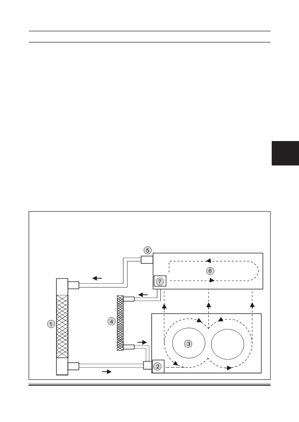
SYSTEM SCHEMATICS
1. Radiator
2. Water Pump
3. Cylinder Block
4. Heater Coil
5.Outlet Elbow
6.Cylinder Head
7.Thermostat