


 135 / 1904

ENGINE 273 MPFI
129
ENGINE
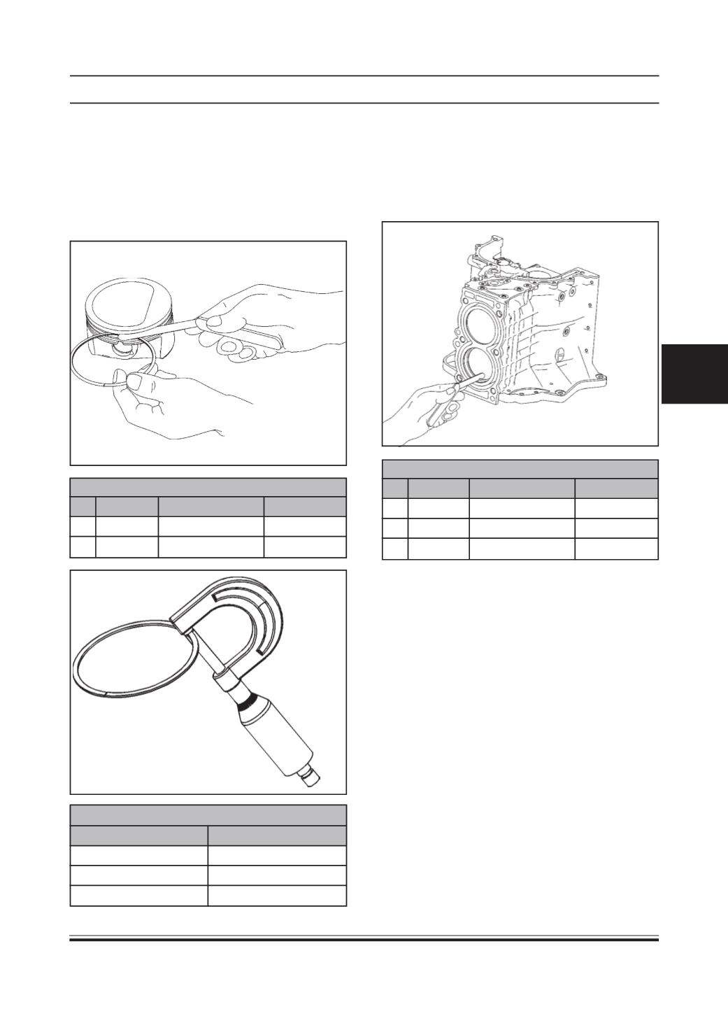
Piston Rings
•
Ring clearance in the groove:
Using a thickness gauge , check each piston ring in
its groove for side clearance and, if the limit stated
below is exceeded, measure the groove width and ring
width to determine whether the piston or the ring or
both have to be replaced.
PISTONRINGCLEARANCE INGROOVE
SR. ITEM STD VALUE
LIMIT
1. Top ring 0.03 to 0.07 mm 0.12 mm
2. 2nd ring 0.02 to 0.06 mm 0.1 mm
PISTON RING THICKNESS
TYPEOFRING
RINGSTHICKNESS(MM)
1st Compression Ring 1.2
-0.01-0.03
2nd Compression Ring 1.2
-0.01-0.03
3rd Oil Control Ring 2.0
-0.03-0.13
•
Piston ring end gap ( butt clearance ):
To measure the end gap, insert the piston ring into the
cylinder bore, locating it at the lowest part of the bore
and holding it true and square; then use a thickness
gauge to measure the gap. If the gap measured ex-
ceeds the limit, replace the ring.
PISTON RING END GAP
SR. ITEM STD VALUE LIMIT
1. Top ring 0.15 to 0.3mm 0.7 mm
2. 2nd ring 0.3 to 0.5 mm 0.7 mm
3. Oil ring 0.2 to 0.7 mm 1.8 mm
•
Butt clearance of piston ring should be measured
in unworn portion of cylinder bore.
•
In case of any piston ring with any defect, com-
plete ring set should be replaced.
•
When cylinder bores are re-bored or honed, pis-
tons and rings of appropriate size should be used.
•
Stagger piston rings gaps such that they are 120°
apart. (With butt gap not in line with piston pin).