


 136 / 1904

130
ENGINE 273 MPFI
•
Big-end thrust clearance:
Check the big end of each connecting rod for thrust
clearance, with the rod fitted and connected to its crank
pin in the normal manner. If the clearance measured
is found to exceed the limit, the connecting rod or the
crankshaft, whichever is responsible for the exces-
sive clearance, must be replaced.
SR. ITEM STD VALUE
LIMIT
a Axial Play 0.05 to 0.35 mm 0.4
•
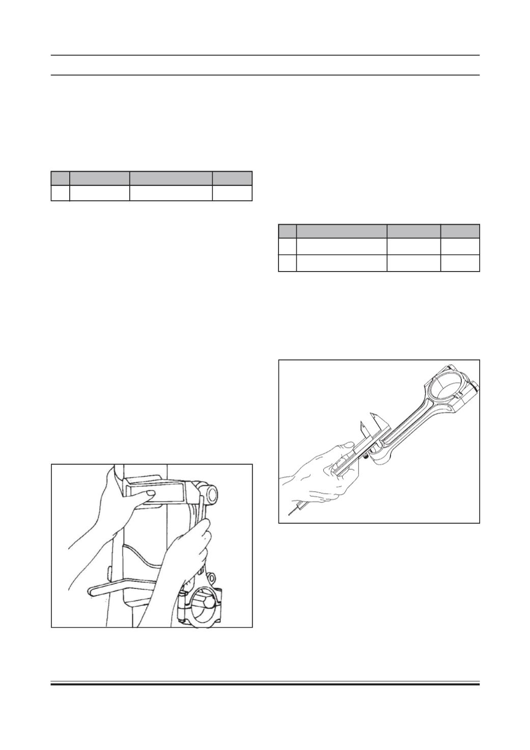
Connecting rod alignment :
Mount the connecting rod on the aligner to check it for
bow and twist and, if the limit is exceeded, replace it.
Ensure that connecting rod big end and small end
axes are parallel to each other and are within speci-
fied limits. Ensure that centre distance between small
end to big end is maintained within specified limit.
Install connecting rod bearing caps without bearing
shells on connecting rod.
Tighten connecting rod bearing cap mounting nuts to
specified torque.
Ensure that identification numbers for connecting rod
and connecting rod bearing cap are matched and
notches for bearing shells are on the same side.
Check twist and bend of connecting rod by using new
piston pin in connecting rod small end.
Measure twists and bends of connecting rod with feeler
gauge with respect to vertical face of connecting rod
alignment gauge in vertical and horizontal plane at a
distance of 50 mm from line joining centers of
connecting rod small end and big end bosses.
If necessary, straighten connecting rod in cold condi-
tion. Since a slight clearance exists between connect-
ing rod bolts and corresponding connecting rod bear-
ing cap holes, it is possible that connecting rod bear-
ing cap once removed may be installed off center, by
which dimension of connecting rod big end parent bore
will be different in different directions. If there is a dif-
ference noticed in connecting rod big
end parent bore dimension, connecting rod bearing
cap can be centralized by lightly tapping it with mallet
in required direction after slightly loosening connect-
ing rod bearing cap mounting nuts.
SR. ITEM
STD VALUE LIMIT
a Limit on Bow
(at 50mm)
0.03 mm 0.05
b Limit on twist
(at 50mm)
0.05 mm 0.1
Connecting Rod Small End :
Inspect the small end of each connecting rod for wear
and evidence of crack or any other damage, paying
particular attention to the condition of its bush. Check
the piston pin clearance in the small end. Replace the
connecting rod if its small end is badly worn or
damaged or if the clearance exceeds the limit.