


 133 / 1904

ENGINE 273 MPFI
127
ENGINE
INSPECTION & REPAIR DATA
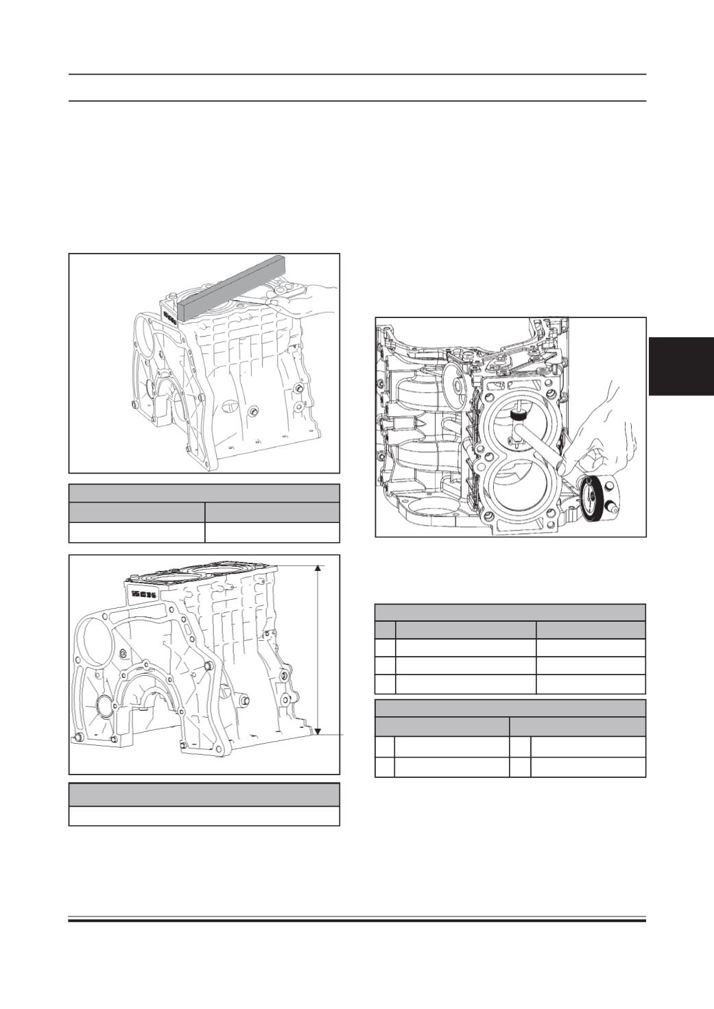
CYLINDER BLOCK:
•
Distortion of gasketed surface
By the samemethod that is prescribed for checking
the distortion of the gasketed surface of the cylinder
head, check the top face of the cylinder block for
distortion and, if the distortion is found to exceed
the limit, machine the face with a surface grinder.
DISTORTIONOF GASKETED SURFACE
STANDARDVALUE
LIMIT
0.02 mm
0.05 mm
CYLINDERBLOCKHEIGHT
242 mm
•
Cylinder bore
Clean the cylinder bore thoroughly. Check cylinder
bore diameter, taper and ovality. Using a cylinder
bore gauge, measure the diameter of each bore in
two directions, longitudinal and transverse, at three
places, top, middle and bottom, to obtain a total of
6 readings. On the basis of these readings taken
on each bore, determine whether the maximum
difference in diameter between any two bores
exceeds the limit. If the limit, stated below, is
exceeded or if the bore wall is badly scored or
burned, re-bore all cylinders to the next oversize
and use oversize pistons in engine reassembly.
If any one of the two cylinders has to be re-bored, re-
bore both the cylinders to the same next oversize.
This is necessary for the sake of uniformity and
balance.
BOREDIAMETER
STANDARDVALUE
WEAR LIMIT
A 73.495 to 73.505 mm 73.555 mm
B 73.505 to 73.515 mm
73.565 mm
C 73.515 to 73.525 mm
73.575 mm
REBORINGDIAMETEROF CYLINDER
STANDARDVALUE OVERSIZE (0.25)
A 73.495 - 73.505 mm P1 73.745 - 73.755 mm
B 73.505 - 73.515 mm Q2 73.755 - 73.765 mm