


 138 / 1904

132
ENGINE 273 MPFI
Connecting-Rod Big End Bearings
Inspect the bearing shells for signs of fusion, pitting,
bum or flaking and observe the contact pattern.
Bearings found in defective condition through this
inspection must be replaced.
Bearing shells are not meant to be repaired by
scrap or grinding with sandpaper or by any
machining. The remedy is to replace them.
If the limit, indicated above, is exceeded, re-grind the
crank- pin to the undersize and use the undersize
bearing, both of which are stated below:
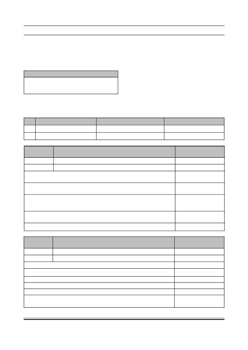
CAUTION
SR. ITEM
STD.VALUE
UNDERSIZE(0.25)
1.
Crankpin diameter
39.98 - 39.995
39.73 - 39.745
2.
Bearing clearance
0.015 - 0.058
0.015 - 0.058
Stage
Connecting Rod small end
BushOutside
Parent bore diameter (mm)
diameter (mm)
Standard
17.006 to 17.017
NA
Repair
NA
NA
Max. permissible circularity & ovality of connecting rod small end parent bore
NA
0.008 mm
Connecting rod small end bush inside dia. (to be finished after installation)
NA
(Piston pin oiled has thumb push fit in small end bush)
Max. permissible out of parallelism (bend) between connecting rod small end &
0.03 mm
big end parent bores measured at a distance of 50 mm from centre line of
connecting rod big end.
Centre to centre distance between connecting rod small end & big end parent
124.25 ±0.03 mm
bores.
Maximum permissible twist of connecting rod.0.05 mm
Stage
Connecting rod big end dia.
Crank pin journal
with bearing shell assembled (mm)
diameter (mm)
Standard
40.010/40.038
39.980 to 39.995
Repair 1
NA
NA
Repair 2
NA
NA
Bearing shells to be selected such that clearance is maintained as
0.015-0.058 mm
Max. permissible difference in weight of connecting rods in one engine
5 gms
Connecting rod big end axial play
0.05 - 0.35 mm
Connecting rod big end parent bore dia.
Ø 43+0.016 mm
Max. permissible taper & ovality of connecting rod big end parent bore
0.01 mm
cylindericity.