


 112 / 1904

106
ENGINE 273 MPFI
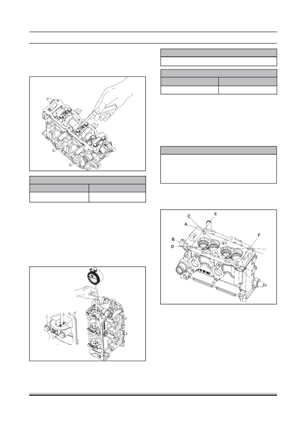
• Thrust Clearance:
Using a thickness measure gauge, measure the
clearance as shown in fig. If the limit is exceeded,
replace the camshaft or camshaft bearing caps.
CAMSHAFT THRUSTCLEARANCE
STANDARDVALUE
LIMIT
0.1 to 0.3 mm
0.4 mm
• Journal wear:
Measure the journal diameter in two directions at
two places to obtain four readings on each journal
and check the journal bores with a bore gauge,
producing four readings on each. From these
readings, compute the radial clearance (Camshaft
journal clearance). If the service limit is exceeded
by any of the computed radial clearances, replace
the camshaft as necessary, cylinder head too.
JOURNALDIAMETER
26.007 mm to 26.02 mm
JOURNAL ANDCAMSHAFT CLEARANCE
STANDARDVALUE
LIMIT
0.027 to 0.053 mm
0.1 mm
Cylinder Head
De-carbon cylinder head:
Deposits of carbon will be found on its combustion
chamber surfaces and exhaust ports. Remember,
overheating tendency and loss of output are often due
to excessive carbon accumulation. De-carbon valves,
too.
NOTE
Do not use any sharp-edged tool to scrape off
carbon. Be careful not to scuff or nick metal
surfaces when decarbonizing. This applies to valves
and valve seats, too.
Distortion of gasketed surface:
Using a straightedge and thickness gauge, check the
flatness at a total of 6 locations.
If the limit, stated below, is exceeded, correct the
gasketed surface with a surface plate and abrasive
paper of about # 400 (waterproof silicon carbide
abrasive paper). Place the paper on and over the
surface plate and rub the gasketed surface against
the paper.