


 437 / 1575

TRANSFER CASE
42
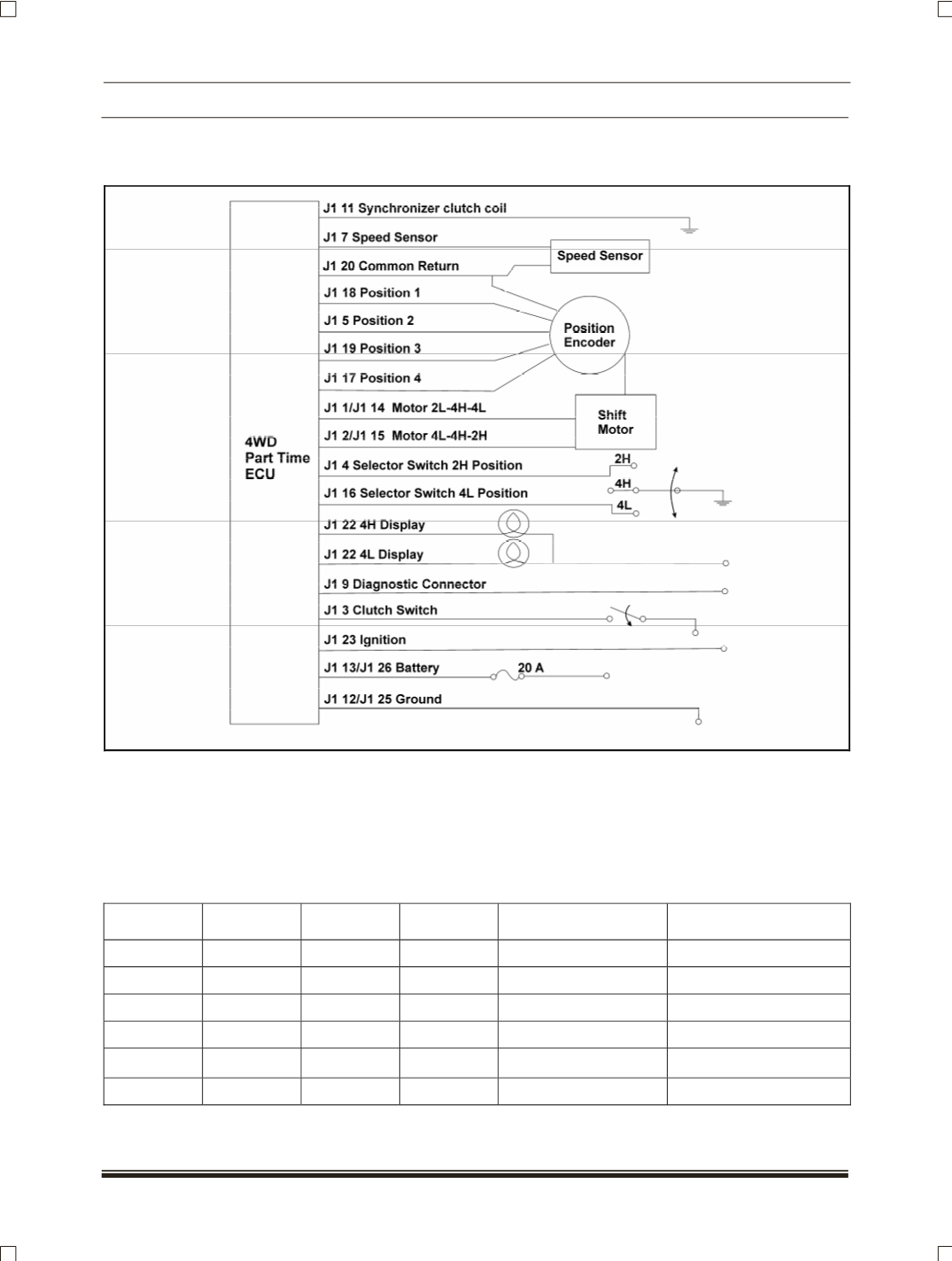
4.3.4 DIAGNOSTIC OF ECU
ECU block diagram
ECU detects transfer case system malfunctions and indicates malfunctioning part
(s)
through flashing indictor
lights. The operator will be alerted of fault condition by continuous illumination of both 4WD HI and 4WD LO
lights on dashboard when ignition is ON.
A service connector is provided to indicate the fault codes in binary. Connect one end to the pin hole number
9 in ECU connector and other end to the ignition switch
(pin no. 23).
The flashing of indicator light will show
the defective code
(As illustrated in the table)
. Identify the malfunctioning part and replace it.
L1
L2
L3
Binary
code
Decimal
Equivalent
Fault With
Off
Off
On
001
1
ECU Module
Off
On
Off
010
2
Shift Motor
Off
On
On
011
3
Synchronizer clutch
On
Off
Off
100
4
Speed Sensor
On
On
Off
110
6
Selector Switch
On
On
On
111
7
Motor Position Switch