


 400 / 1575

TRANSFER CASE
5
TANSFER CASE
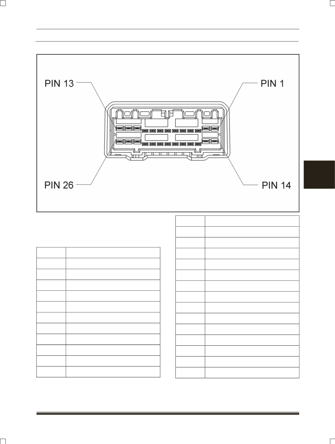
A. CONNECTOR
NOTE
For connection details of Transfer case ECU refer
A3 book of electrical section.
PINOUT
PIN NO.
PIN DETAIL
1
Motor LO-HI
2
Motor HI-LO
3
Trans Neutral
4
2/4 Switch
5
Position 2
6
Not Used
7
Speed
8
Not Used
9
Diagnostic Display
10
4L Display
11
Clutch
12
Ground
13
Battery
14
Motor LO-HI
15
Motor HI-LO
16
HI-LO Switch
17
Position 4
18
Position 1
19
Position 3
20
Common Ground
21
Not Used
22
4H Display
23
Ignition
24
FAD Signal
25
Ground
26
Battery