


 397 / 1575

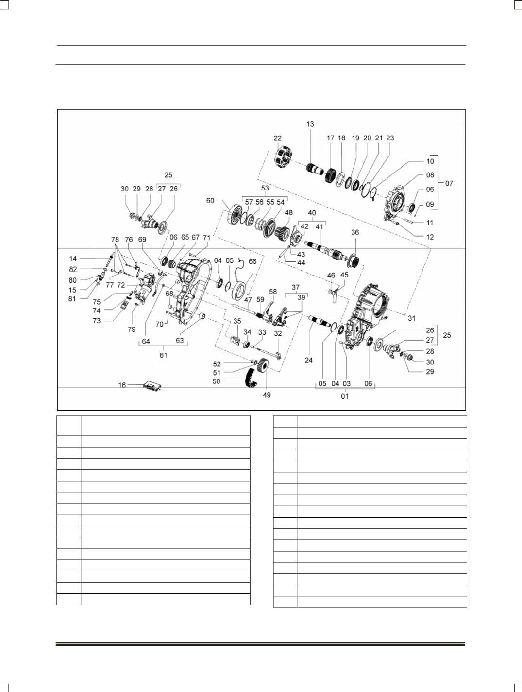
TRANSFER CASE
2
4.3.1.2 CONSTRUCTION
In transfer case power is received by input shaft, which is coupled with output shaft of transmission gear box
by matching splines. There are two outputs, one for rear wheels and the other for front wheels.
SR.
NO. DESCRIPTION
01 Assembly- case
03 Spring dowel bushing
04 Bearing – annular
05 Ring – retaining
06 Seal – oil
07 Assembly - front adapter
08 Adapter
09 Pin - spirol
10 Snap - ring
11 Stud - mounting
12 Bolt - indented hex. Washer head
13 Assembly - input shaft & bearing
14 Assembly - speedo gear
(Driven)
15 Bolt - hexagonal Cap screw
16 Assembly – controller
17 Gear – sun
18 Plate - carrier thrust
19 Washer - thrust
20 Bearing annular
21 Ring – retaining
22 Assembly - carrier complete
23 Ring – snap
24 Shaft - lower output
25 Assembly -yoke
26 Deflector-dust
27 Yoke - single carden
28 Seal – oil
29 Washer
30 Lock nut
31 Assembly - breather
32 Shaft - shift
33 Spacer