


 149 / 1575

ENGINE
110
2.1.5 COOLING SYSTEM
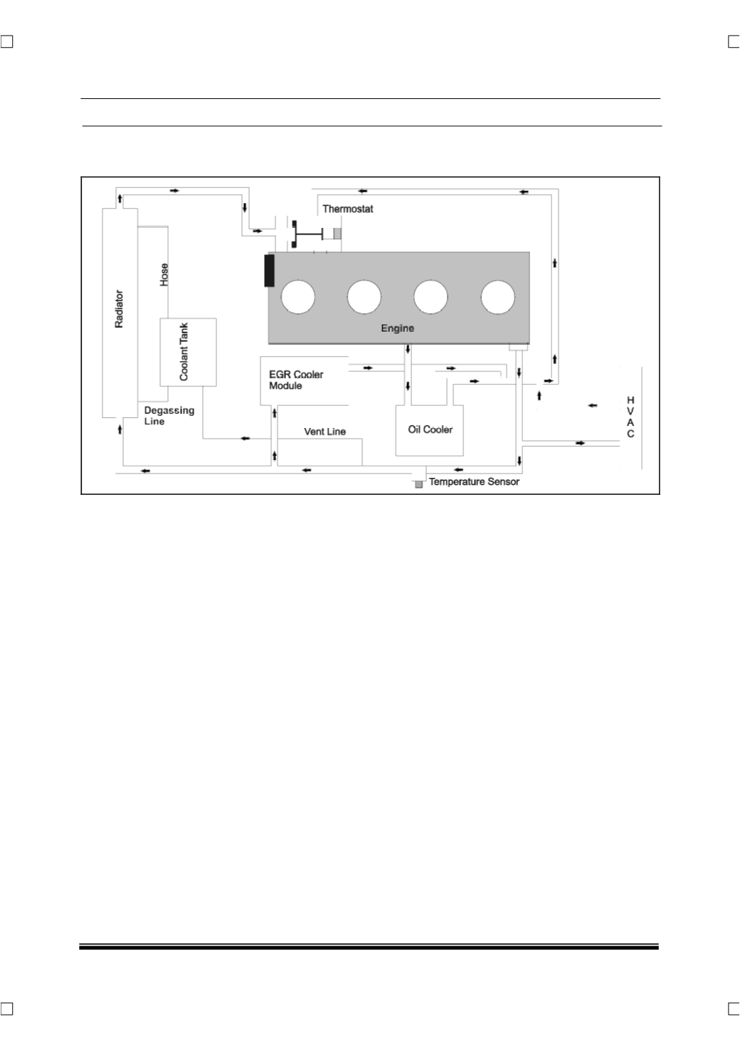
2.1.5.1 SYSTEM DESCRIPTION:
The above figure gives the coolant flow circuit with
the components. The coolant flow is controlled by
the thermostat
(For details refer Thermostat in next
section).
In addition to the Cylinder head and block,
the coolant also circulates through Oil cooler, HVAC
heater coil and EGR Cooler
.
An auxiliary coolant tank is provided to compensate
for the drop in coolant level. In addition there is a de-
gassing line and a vent line connected to it. These
help in maintaining the system pressure created by
expansion and contraction of the coolant.