SUSPENSION
38
6.10 WHEELS AND TYRES
Wheels and tyres assembly is an important part in
the vehicle; it has effect on performance of the
vehicle.
It is responsible to transfer the required road feel
to the driver and passengers. Hence it is required
to follow correct workshop practices.
A) TYRE INSPECTION
Inspect the tyre for the following and replace if
found.
a) Bulge on threads and side walls.
b) Cuts, cracks, abnormal, excessive, and Un-
uniform tyre wear.
B) REPLACEMENT OF TYRES:
When replacement is necessary, the original
equipment type tyre should be used.
Replacement tyres should be of the same size,
load range, and construction as those originally
on the vehicle. Use of any other size or type tyre
may affect ride, handling, speedometer/ odometer
calibration, vehicle ground clearance and tyre
clearance to the body chassis.
It is recommended that new tyres be installed in
pairs on the same axle. If necessary to replace
only one tyre, it should be paired with the tyre
having the most tread, to equalize braking
traction. Also do not mix different types of tyres
(viz. radial, bias etc) on the same vehicle,
because it badly affects the handling of the
vehicle.
C) REPLACEMENT OF WHEELS:
Wheels must be replaced if
1) They are bent,
2) Dented,
3) have excessive lateral or radial run out,
4) Air leak through welds,
5) Have elongated bolt holes,
6) If wheel bolts will not stay tight, or
7) If they are heavily rusted.
Wheels with greater run out than specification
may cause vibrations.
Replacement wheels must be equivalent to the
original equipment wheels in load capacity,
diameter, rim with offset and mounting
configuration. A wheel of improper
Size or type may affect wheel and bearing life,
break cooling, speedometer/odometer calibration,
vehicle ground clearance, and tyre clearance to
body and chassis.
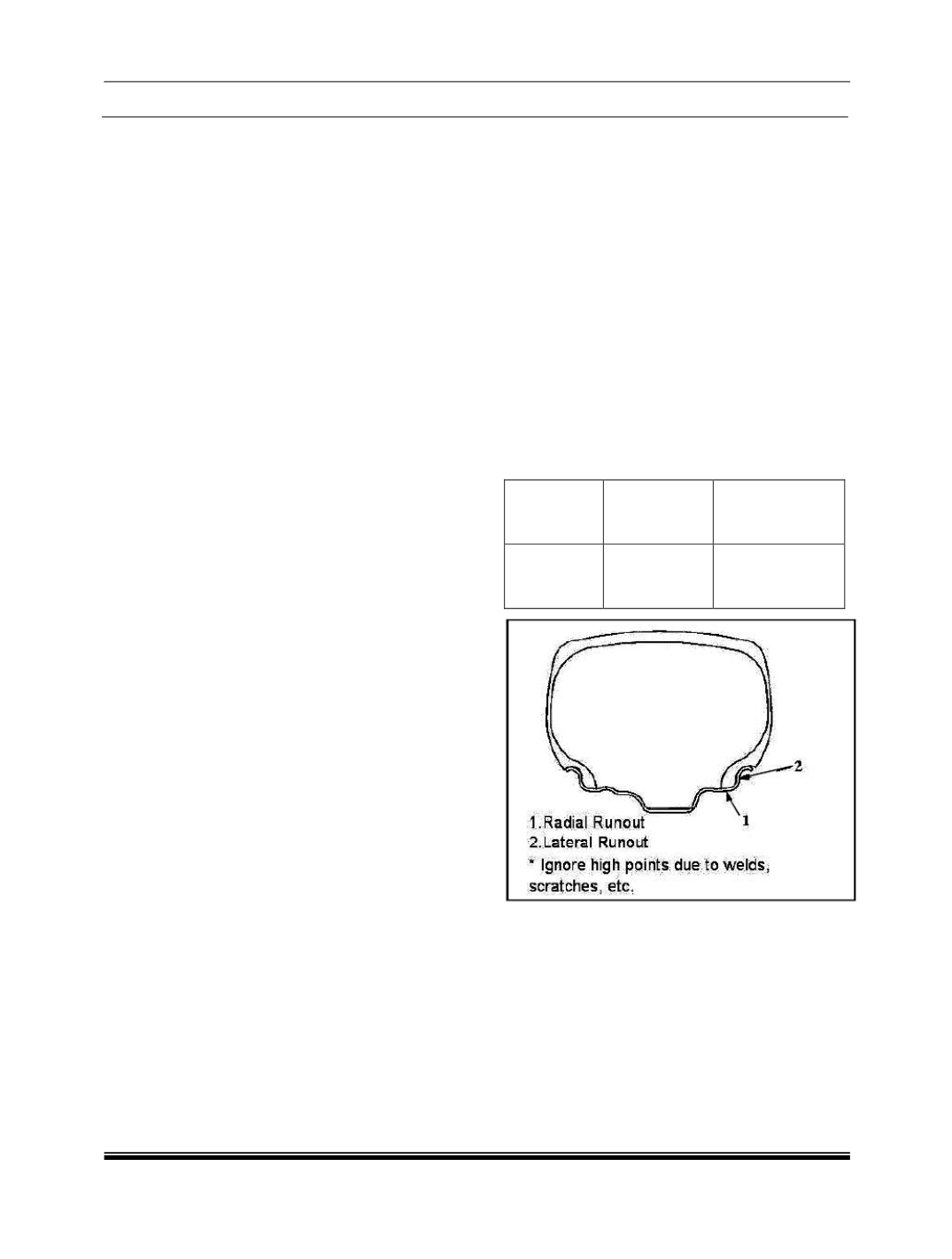
6.10.1 HOW TO MEASURE WHEEL RUNOUT:
To measure wheel run out, it is necessary to use
an accurate dial indicator. The tyre may be on or
off the wheel. The wheel should be installed on a
wheel balancer for proper measurement.
Take measurements of both lateral run out and
radial run out at both inside and outside of the rim
flange. With the dial indicator set in place
securely, turn the wheel on full revolution slowly
and record every reading of the indicator. fig
When the measured run out exceeds the
specification and correction by the balancer
adjustment is impossible, replace the wheel. If the
reading is affected by welding, paint or scratch, it
should be ignored.
Radial
Run out limit
Lateral
Run out limit
Steel wheel
/alloy wheel
1.14 mm
(0.045 in)
1.4 mm
(0.055 in)
MATCHED TYRES AND WHEELS:
Tyres and wheels are match mounted at the
assembly plant. This means that the radially
stiffest part of the tyre or “high spot” marked in
RED on tyre is matched to the smallest radius or
“low spot” of the steel wheel rim. In case of alloy
rims valve is to be matched with YELLOW spot on
the tyre. The YELLOW spot is an indication of low
point of static imbalance of tyres. This is done to
provide the smoothest possible ride. The color
spots on the tyres are originally marked by paint
dot on the out board sidewall. This paint dot will
eventually get wash off the tyre.


