DRIVETRAIN C549
37
H. TRANSAXLE AS+SEMBLY
INSTALLATION
1. Fit the guide pin for fitting Reverse and secure
it with exterior staking.
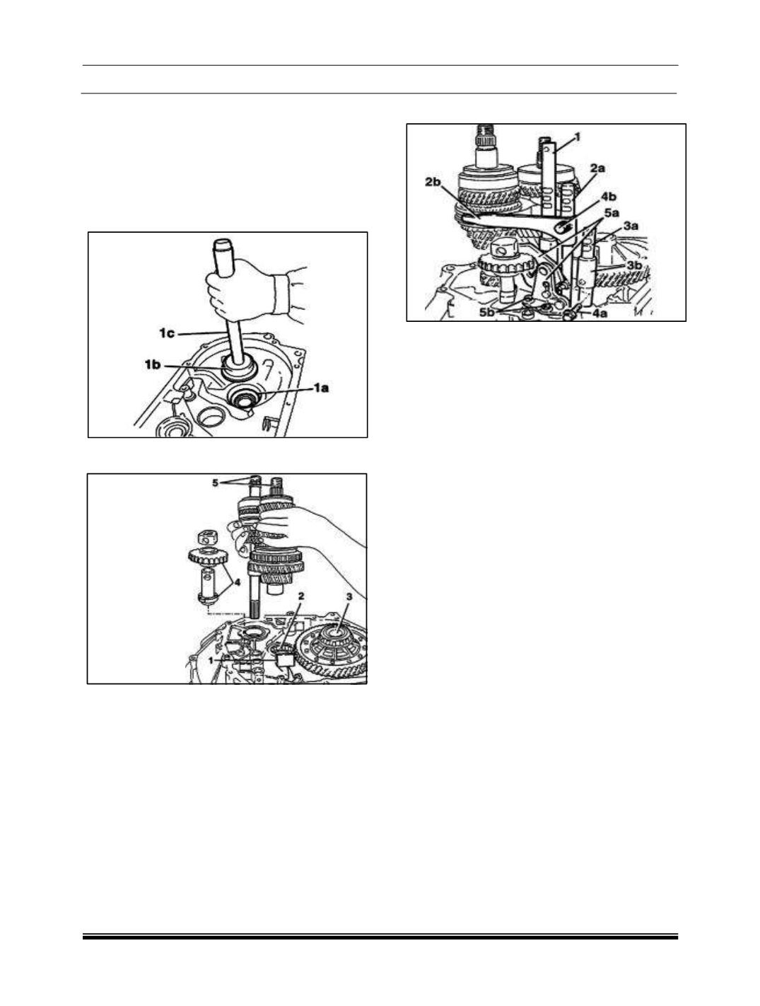
2. Fit the differential mounting bearing outer
races (1a) using tools (1b) 287458902617
(Fitting tool) and (1c) 287458902618 (Grip).
3. Fit the magnet (1).
4. Fit the lay shaft (2) front bearing.
5. Fit the differential (3) assembly.
6. Fit the reverse idler gear (4).
NOTE: Make
sure that the gear engagement
teeth are facing downwards.
7. Fit the main and lay shaft assemblies (5) at the
same time.
8. Fit the gear engagement safety pawls using a
suitable drift.
9. Fit the 5th speed and reverse drive rod (1).
10.Fit the 3rd - 4th speed control fork (2a) and the
control rod (2b).
11.Place the safety pawl on the rod before fitting it
in its housing
12.Remove the 1st-2nd speed drive rod (3a)
together with the fork (3b).
NOTE
:
To facilitate installation, move the 1st-
2
nd
speed control rod in the arrowed direction.
13.Tighten the M6 bolts securing the 1st-2nd
speed control forks (4a) and the M6 bolts 3rd-
4th speed control rods (4b), both to a specified
torque of1.5 ~ 1.9 da Nm.
14. Fit the reverse control fork mounting bracket
(5a) and secure it tightening the M6 bolts (5b)
to torque of 8.5 ~ 11.1 da Nm.
15.Place all the gear control forks in neutral.
16.Apply sealant to the contact surfaces between
the manual TRANSAXLE bell housing and the
TRANSAXLE casing.
17.Fit the TRANSAXLE casing on the manual
TRANSAXLE bell housing.
NOTE
:
Keep the gear selector/engagement
lever upwards and check that the gear selector
engages in the 3rd-4th speed control fork.
18.Tighten the TRANSAXLE casing M8 bolts to
Torque of 2.1 ~ 2.6 Kgm
19.Fit the gear control rod positioning plugs
20.Tighten the reverse shaft M8 bolt to the
recommended torque of 2.9 ~ 3.6 Kgm.
21.Fit the reversing light switch.
22.Fit the main and lay shaft rear bearing circlips.


