


 129 / 801

LV ELECTRICAL SYSTEM
43
REMOVAL
1. Gently pry out the drive mode switch.
2. Disconnect the electrical connection.
REFITMENT
For refitment follow the removal procedure in
reverse.
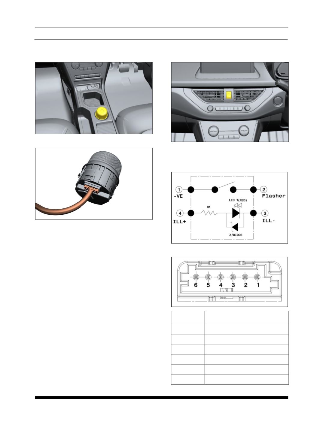
9. HAZARD SWITCH
LOCATION
When the switch is pressed, hazard waning
indicators start flashing.
A. CIRCUIT DETAILS
B. PINOUT DETAILS
PIN
DESCRIPTION
1
-VE
2
FLASHER
3
ILLUMINATION -
4
ILLUMINATION +
5
NC
6
NC