


 888 / 1006

ELECTRICAL
62
PINOUT DETAIL
PIN
DESCRIPTION
1A
2A
ACC
3A
1B
2B
3B
GND
4B
4A
BCM INPUT (Applicable for mirror fold
only)
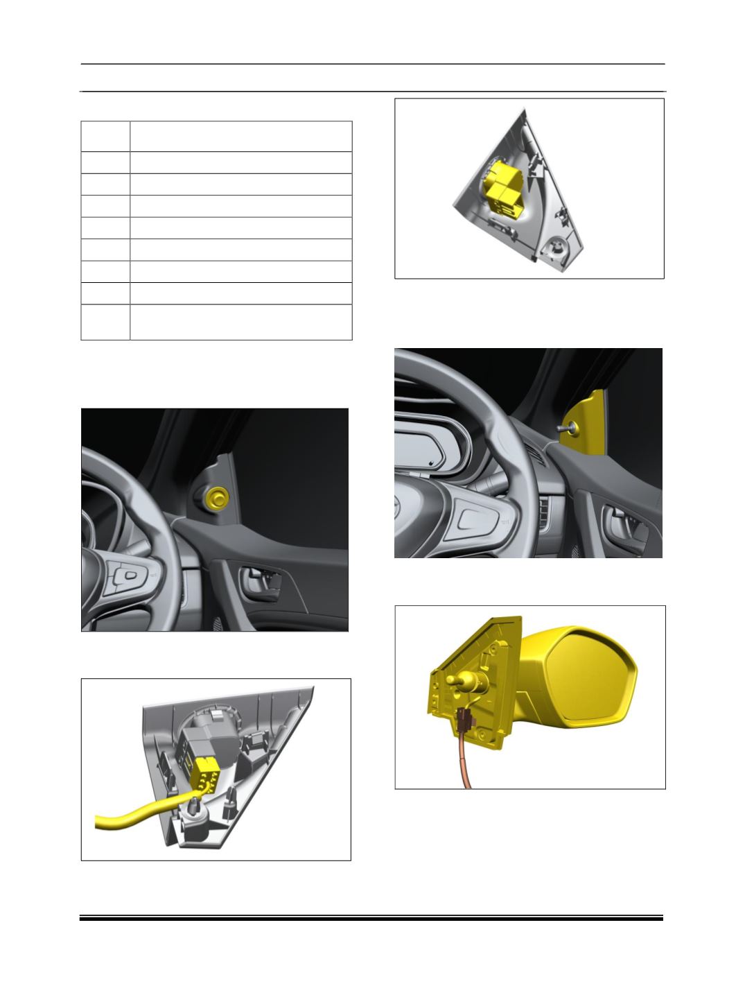
REMOVAL (High Version)
1.Pry out the Mirror adjustment switch cover from
cheater assembly.
2.Disconnect the electrical connection of mirror
adjustment switch.
3.Take out the mirror adjustment switch
.
REMOVAL (If Applicable)
1. Pry out the Mirror adjustment inner ORVM
cover from cheater assembly.
2. Disconnect the electrical connection of mirror
adjustment switch.