


 435 / 745

BRAKES
32
F. BRAKE LIGHT SWITCH ADJUSTMENT
1. Place the brake pedal in release position.
2. Hold the pedal in release condition by one
hand & insert the switch in to the adjuster by
other hand.
3. Insert the switch till the plunger is completely
depressed & body of switch is touch to pedal.
4. Turn the switch at that moment to clockwise.
This movement create the gap of 1 mm
between switch & pedal.
5. Ensure the pedal is free & not pressed due to
switch.
G. CALIPER GREASING
Loosen and remove the sliding pin and grease
them with the special grease which is provided for
brakes
.
NOTE
Check the sliding pin boot for any cut or damages.
If any defect is found replace the boot.
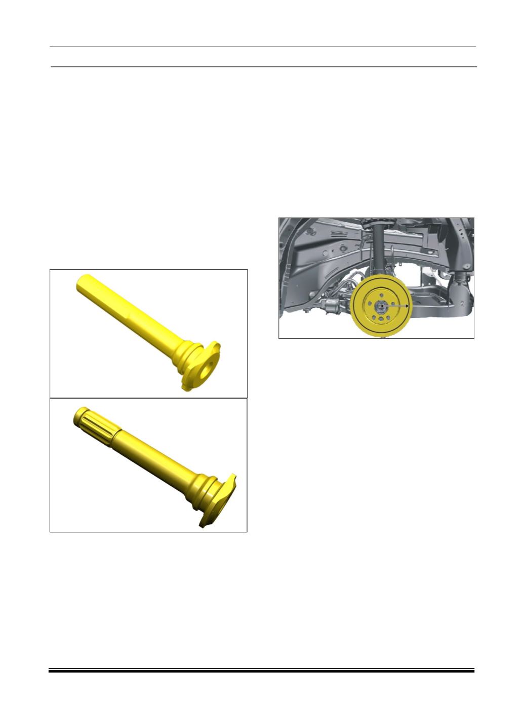
H.
DISC
RUN-OUT
MEASUREMENT
PROCEDURE
1. With the gear in neutral position, hoist the
vehicle on two post lift and remove the front
wheel. Tighten the wheel nuts on Brake disc
only.
2. Mount the magnetic dial stand at an
appropriate position such that the needle can
be placed perpendicular to the disc face.
3. Ensure that brake disc surface is clean and
dial indicator tip touching the brake disc on
circle at a distance of
≈ 114
mm from wheel
center.
4. Rotate the brake disc while watching the dial
indicator needle movement; record the
maximum value shown on the dial indicator.
The maximum value is the brake disc run out.
5. The brake disc runout should not be more than
0.060 mm (60 Microns).
NOTE
For further inspection and repairs refer the
BRAKE DISC REMOVAL in the next section.
DISC INSPECTION:
The disc should be free from score marks. If
scored, it should be replaced.
The disc thickness variation is to be checked by
measuring the thickness of the rotor at four or
more points around the circumference of the rotor.
All measurements must be made at the same
distance from the edge of the rotor.
After fitment, the face runout of the disc should be
less than
0.06
mm.
During measurement, confirm the dial gauge
probe should perpendicular to the disc and under
slight preload.
Check front wheel bearing for looseness before
face runout measurement.
The control of the braking surface finish is
necessary to avoid pulls and erratic performance.
It will also help in extending pad life.