


 324 / 745

DRIVESHAFT (AT)
9
A. Tripot balls
B. Needle rollers
C. Housing
8. Dry all the parts. Inspect these parts for
damage or wear. (If any of the parts are
damaged, the entire sub- assembly along with
the outer housing needs to be replaced.).
9. After this remove the rubber boot from the
axle shaft.
B. TRIPOT JOINT ASSEMBLY:
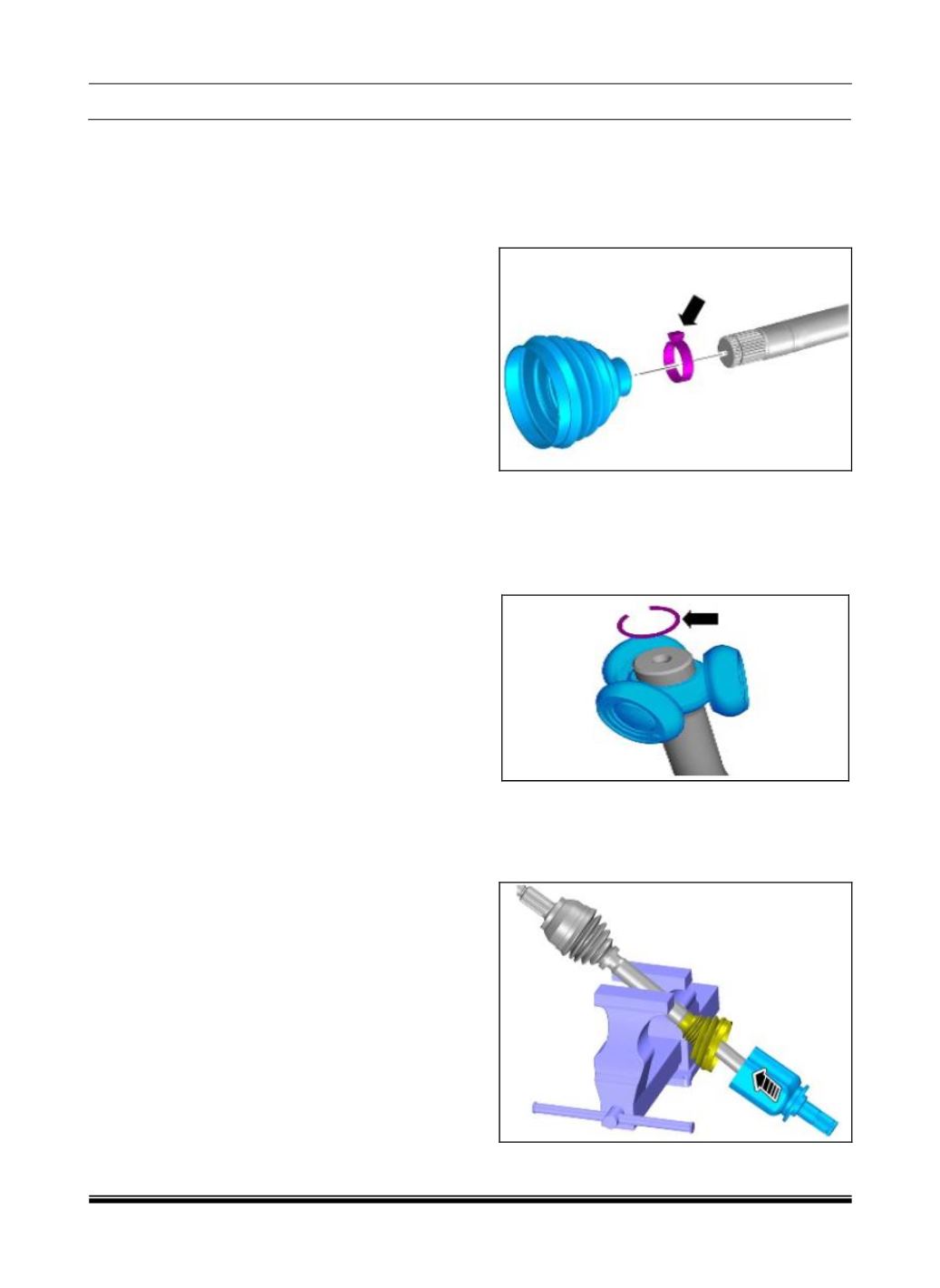
1.Install the new small seal retaining clamp on the
neck of the seal. Do not crimp the small seal
retaining clamp. Slide the tripot seal into the
axle shaft, passing over the seal grooves of the
axle shaft towards the CV end of the axle.
2.Place the tripot spider assembly on to the drive
axle shaft. Assemble the spider assembly to the
axle shaft and tap gently if required. Insert the
new circlip ring using the plier
Important:
Ensure that the ring is fully seated in
the groove on the axle.
3.The inboard joint is to contain 186±10g of
grease. A minimum of 114g of grease is to be
placed inside the tripot housing at the bottom of
the bowl. The balance grease to be placed in
the tripot seal.
Important:
The end of the tripot seal must be next
to the seal stop on the housing.