


 147 / 745

KRYOTEC ENGINE
139
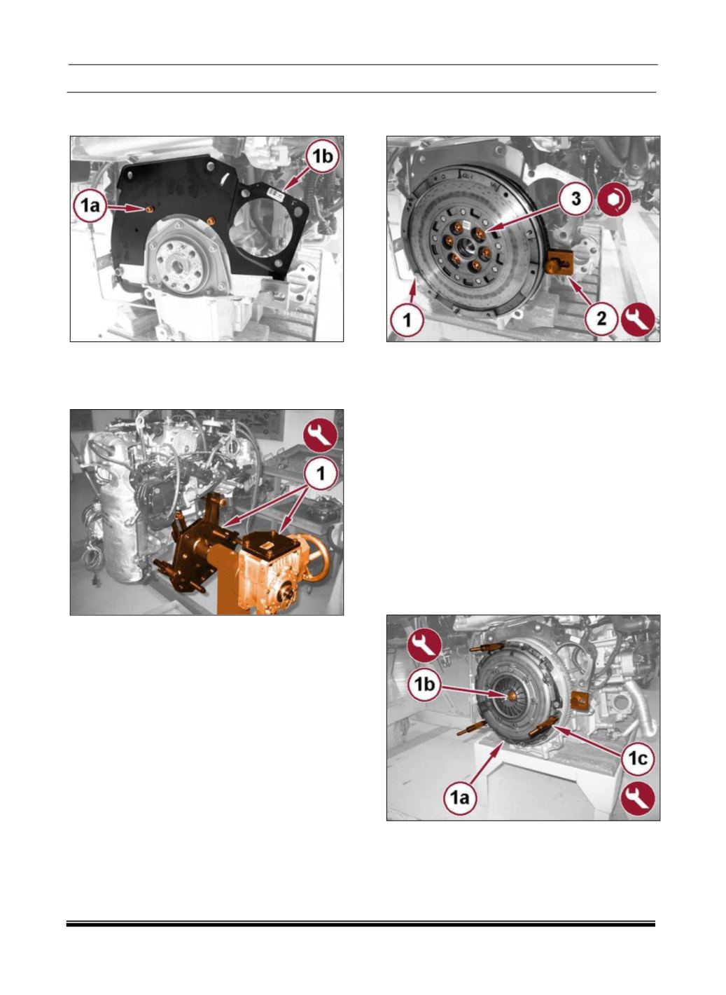
10. Remove the bolts (1a) and the flywheel dust
shield (1b).
11. Remove the 1860846000 flywheel holder tool.
12. With the aid of a hydraulic lift, install the engine
block to the 1871000000 maintenance stand (1).
FITMENT
1. With the aid of a hydraulic lift, remove the engine
from the 1871000000 maintenance stand.
2. Place the engine on a suitable platform.
3. Install the flywheel dust cover with the bolts
tightened to the proper torque specification
(Torque Specifications).
4. Install the flywheel (1) and hand tighten the bolts
(3).
5. Install the 1860846000 flywheel holder tool (2).
6. Tighten the flywheel bolts (3) to the proper
(Torque Specifications).
NOTE
The clutch friction disc is identified with a “MOTOR
SIDE” marking for correct assembly.
To avoid contamination, do not touch the friction
disc surface with bare hands.
Thoroughly clean the friction disc surface of all
corrosion or residue prior to assembly.
7. Position the clutch friction disc and pressure
plate (1a) and install the clutch centering tool
2000030800 (1b) from the tool kit and clutch
compressor mounting posts 2000040925 (1c) tool
kit.