


 139 / 418

1.2L REVOTRON ENGINE
128
8. Assemble the RRF along with Hydraulic Lash
Adjuster from the cylinder head as shown in
below figure.
NOTE
To avoid damage to valve tips, do not
rotate the camshaft.
9. Repeat the procedure for exhaust port, noting
the locations and components for each valve
for proper reassembly.
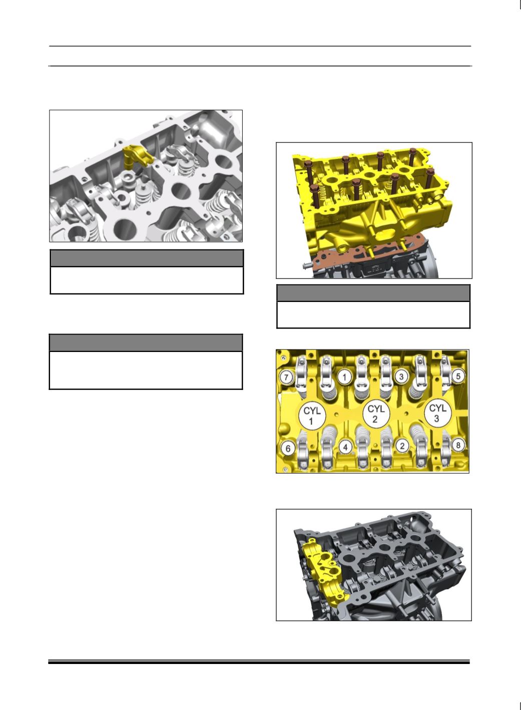
IV. Assembly of Cylinder Head
1. Place the cylinder head on the table.
2. Mount the cylinder head gasket over the
block.
3. Assemble the cylinder head on the block.
NOTE
Match the gasket profile to Cylinder block
surface as shown in figure..
4. Tighten the fasteners as per given sequence.
5. Assemble the lower ITG Bearing Cap with
locating dowels. Ensure the NRV (Non return
valve) in place inside lower ITG.
CAUTION
When assembling the camshaft, use care
to avoid damaging the bearing surfaces of
the cylinder head and the camshaft.