


 99 / 4910

Q501 4 Cylinder MT Application
DTC Troubleshooting Data
Version: 0.1
Date: 21-Sep-2018
Prepared By: Mithi Prasad, Sarang Kulkarni, Manish Gupta
Checked By: Yogesh Jadhav
Approved By: Satish Kumar P
Page: 67 of 1052
Copyright ©
TATA MOTORS Ltd.
This document must not be used in any way, such as copying and redistributing to third parties, without the consent of author.
Step Checks
IF YES
IF NO
1.
Check whether the boost pressure sensor connector is
fitted properly.
Go to next step
Fit connector
properly
2.
Check for electrical continuity between ECU to Boost
pressure sensor connector as per circuit schematic
Go to Step 3
Establish continuity
by rectifying
harness
connections as per
the circuit
schematic
3.
Are there any pins damaged at EMS ECU Connector or
boost pressure Sensor connector?
Replace the connector
or wiring harness
Go to step 4
4
Are there any pins backed out from the EMS ECU
Connector or Boost pressure sensor connector?
Rectify/Replace
Connectors
Go to Step 5
5
Check inlet air circuit for clogging; wrong
assembly/fitment etc; Any issues found?
Clean the inlet air circuit
and remove any
clogging
Go to Step 6
6
Check air leak in intake or exhaust circuit
Rectify/Replace
Connectors/hoses/pipes
Go to Step 7
7
Fault Still Persists?
Replace boost pressure
Sensor. If Fault still
persists then Call Hot
line.
Follow the steps
again for
reconfirmation
DTC’s confirmation:
After rectification, Test Drive the vehicle for 2 KM and ensure that no DTC’s are logged in ECM.
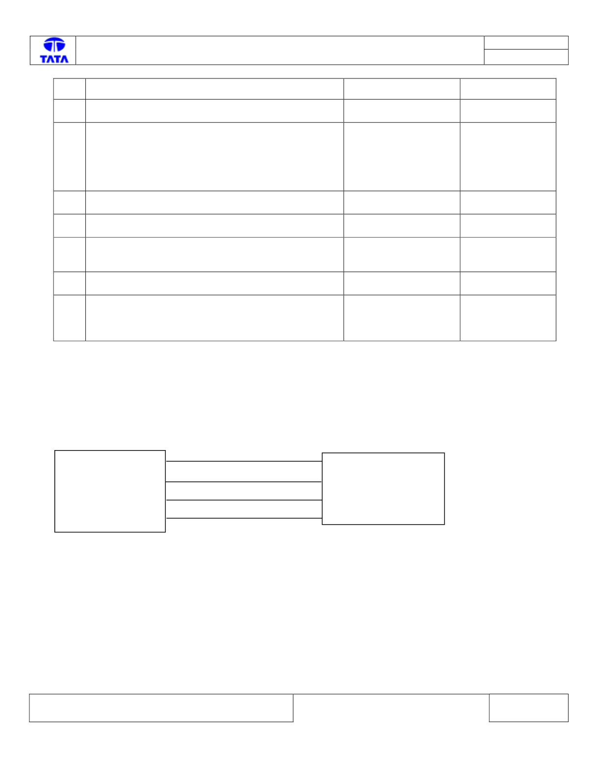
Circuit Schematic:
EMS ECU
A
95
A
61
A
38
A
96
Boost
Pressure Sensor
1
2
3
4
+
5V supply
Boost Pressure signal
Ground
Boost Temp signal