


 837 / 4910

Q501 4 Cylinder MT Application
DTC Troubleshooting Data
Version: 0.1
Date: 21-Sep-2018
Prepared By: Mithi Prasad, Sarang Kulkarni, Manish Gupta
Checked By: Yogesh Jadhav
Approved By: Satish Kumar P
Page: 805 of 1052
Copyright ©
TATA MOTORS Ltd.
This document must not be used in any way, such as copying and redistributing to third parties, without the consent of author.
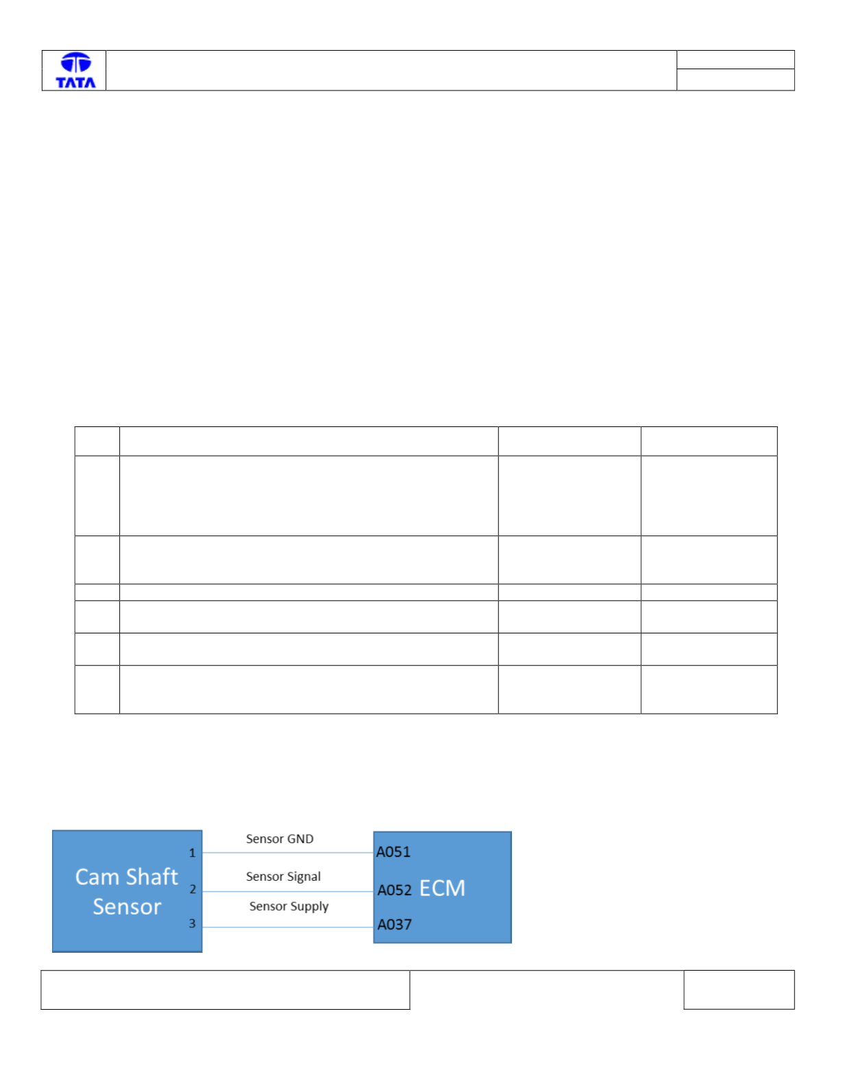
Component Details:
A typical Hall Effect Sensor has three wires or terminals: one for ground, one for supply or reference voltage and one for
the output signal. To produce an output signal, a Hall Effect Sensor must be supplied with a reference voltage. When a
Metal/wheel passes through the air gap between the magnetic field (Magnet) and silicon chip (CAM sensor), it blocks the
Magnetic field and causes the chip’s output voltage to suddenly drop to zero else the chip's output voltage is 4.7 Volts.
Preliminary Checks:
1. Check whether the customer voice / view about the issue is matching with the fault effects mentioned in above
Table. If yes, go ahead with next steps. If not, check for other DTC’s presence.
2. Check whether other customers report similar complaints earlier. If yes, perform the preliminary checks with
respect to earlier issue closure.
3. Camshaft sensor signal / supply / ground pins shorted to Supply or Ground.
4. Loose/ Damaged Connections between Cam shaft Sensor and EMS ECU.
5. Check for damage / back out of pins at ECU connector.
6. Check for damage / back out of pins at cam shaft sensor’s connector.
Trouble Shooting:
Step Checks
IF YES
IF NO
1
Is there wiring harness electrical continuity between ECU
pin A037 & Cam Shaft sensor pin 3, ECU pin A052 and
Cam shaft sensor pin 2, ECU pin A051 and Cam shaft
sensor pin 1.
Go to next step
Rectify the wiring
harness
connections as per
the circuit
schematic.
2
Check whether the ECM pins A037, A052, A051 are either
short circuited to Battery Supply / Ground
Request Driver on
not to over-speed
vehicle
Go to next step
3
Check whether the cam shaft sensor is damaged
Call hotline
Go to Next Step
3
Are there any pins backed out from the Cam shaft sensor
Connector
Rectify/Replace
Connectors
Go to Next Step
4
Are there any pins backed out from the EMS ECU
Connector
Rectify/Replace
Connectors
Go to Next Step
5
Fault Persists.
Call Hotline
Repeat the above
steps for re-
confirmation
DTC’s confirmation:
After rectification, Test Drive the vehicle for 2 KM and ensure that no DTC’s are logged in ECM.
Circuit Schematic: