


 4862 / 4910

Immobilizer –DTC Troubleshooting Data
Version: 1.
2
Date:
03-June-2014
Prepared Author
:
Sarang K/Mithipati P
Review & approved by
: R A Rode (ERC-E&E)
Page: 19 of 67
Copyright ©
TATA MOTORS Ltd.
This document must not be used in any way, such as copying and redistributing to third parties, without the consent of author.
Select the electronic key
The Status of immobilizer should be as follows:
Immo code programmed in EMS
Engine starting enable
Valid keys detected & Authentication successful
CAN communication Ok
Circuit Schematic Diagram:
Refer the immobilizer schematic
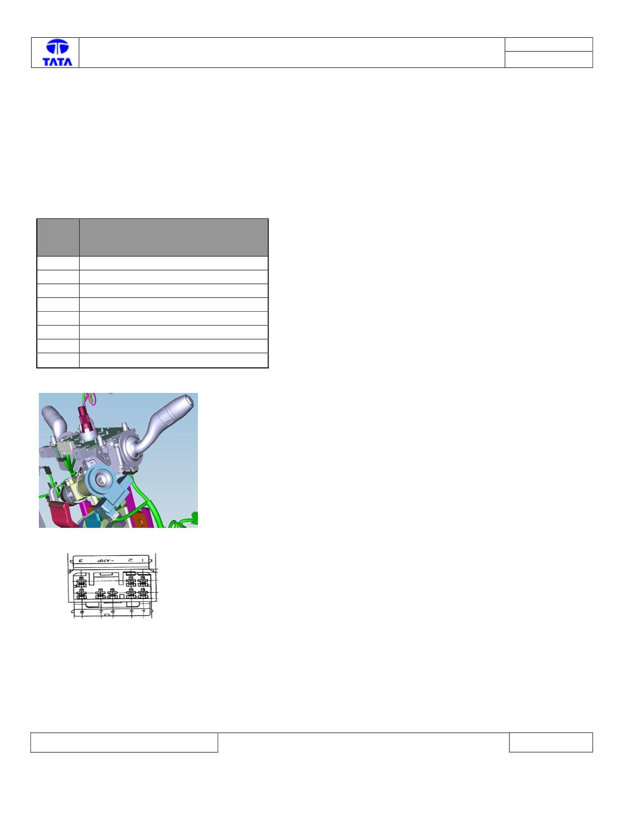
VICM
pin
no
Pin description
1
Vbatt (KL30)
2
GND
3
CAN_H(High-speed)
4
Ignition (KL15)
5
Status LED
6
Trasport Mode Fuse (10A)
7
Battery Supply (+Vbatt)
8
CAN_L(High-speed)
Component Location & Image:-
Connector View & Information: -