


 4492 / 4910

Copyright ©
TATA MOTORS Ltd.
This document must not be used in any w ay, such as copying and redistributing to third parties, w ithout the consent of author .
SRS / Airbag
ECU – DTC Troubleshooting Guide
Version: 14.0
Date: 14-February-2017
Prepared by:Airbag COC Review &
Approved by:Sanjeev VM
Page: 223 of 549
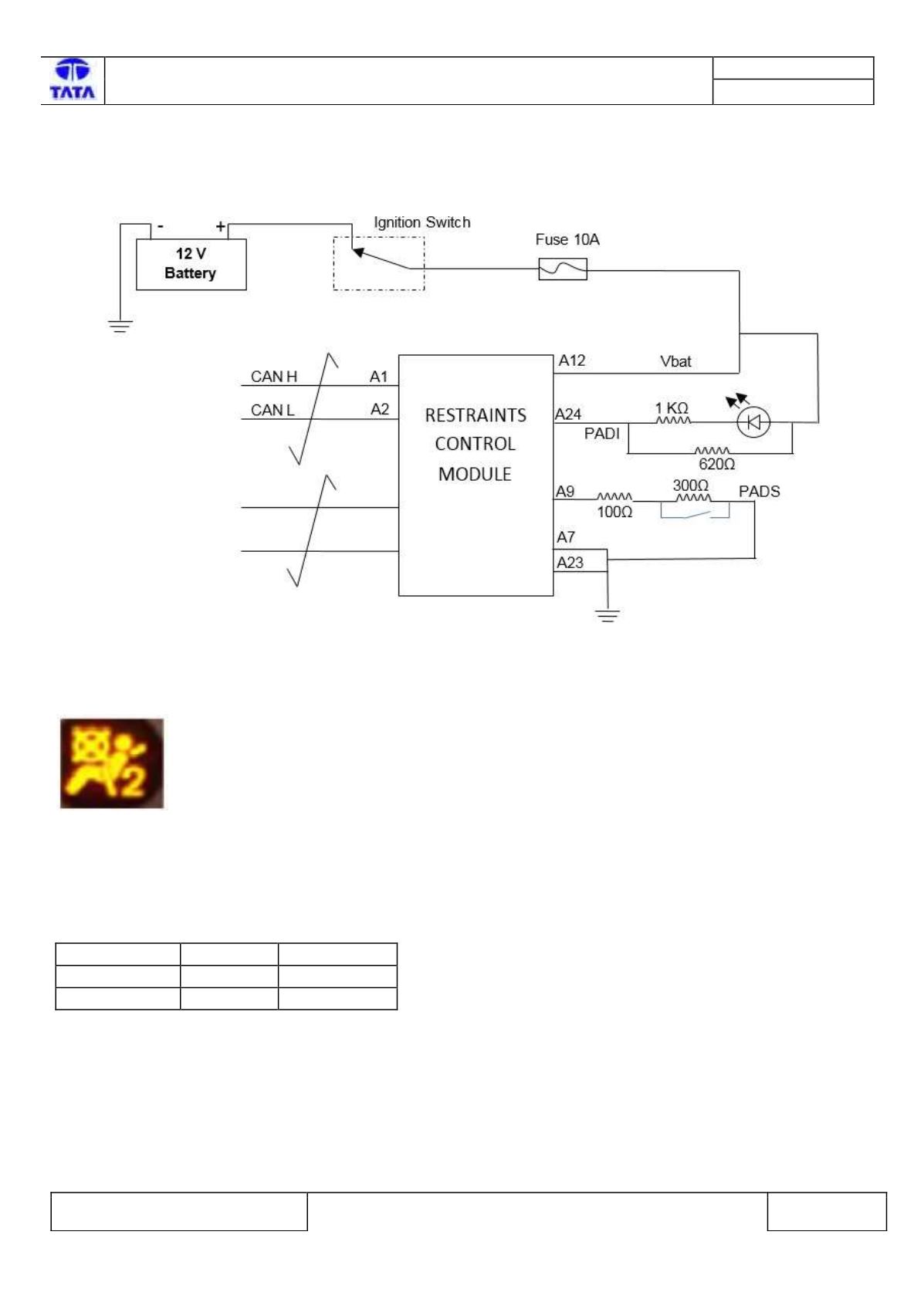
Circuit Schematic Diagram:-
Schematic shown below for illustration
Battery>>>>>Fuse>>>>Relay>>>>>>>Sensor/Actuator>>>>>ECU
Component Location & Image:-
PAD Indication is present in the Instrument cluster or in SBR display.
Fig204:- PAD indication
Connector Location:-
The Chamber Coding & color are:
Chamber
Coding
Color
Chamber A
D
Blue
Chamber B
C
Brown