


 4348 / 4910

Copyright ©
TATA MOTORS Ltd.
This document must not be used in any w ay, such as copying and redistributing to third parties, w ithout the consent of author.
SRS / Airbag
ECU – DTC Troubleshooting Guide
Version: 14.0
Date: 14-February-2017
Prepared by:Airbag COC Review &
Approved by:Sanjeev VM
Page: 79 of 549
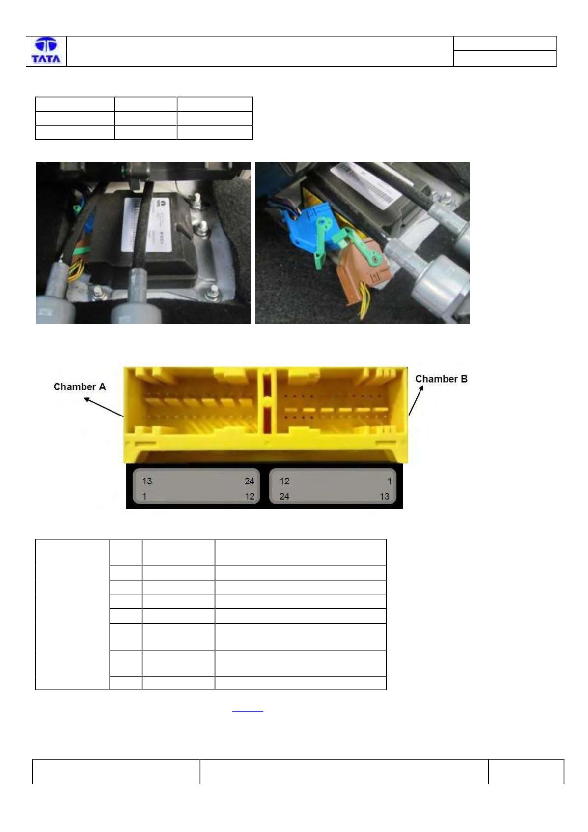
Connector Location:-
The Chamber Coding & color are:
Chamber
Coding
Color
Chamber A
D
Blue
Chamber B
C
Brown
Connector View & Information:-
Fig76:- Airbag ECU connector interface.
Pin
No.
Pin Name
Description
1
CAN_H
CAN High
2
CAN_L
CAN Low
7
A_GND
Common Switch GND
12 Vbat
Supply Voltage Battery
21 BTFP+
Belt Tensioner Front Passenger,
Plus
22 BTFP-
Belt Tensioner Front Passenger,
Minus
23 GND
Power GND
Please refer Airbag ECU Pin Assignment on
Page 6 for more details.
Inspection Method:-
N.A.
Airbag ECU is fitted in the floor of central console in the car.
.
CHAMBER A
Fig:74 Airbag ECU location Fig:75 Airbag Wiring Harness connector