


 482 / 948

HVAC
47
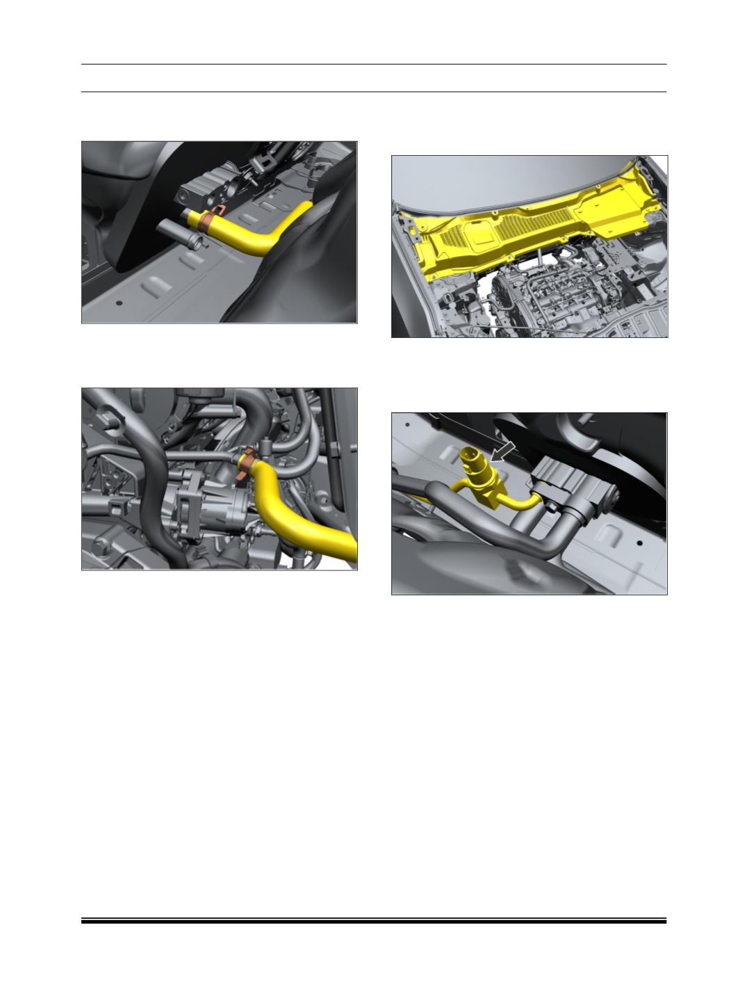
b) HEATER INLET HOSE ASSEMBLY
1. Remove clamp spring band from firewall side.
2. Remove quick connector from engine side.
3. Remove hose clamps attached to the firewall as
shown in below figure.
4. Remove outlet hose.
FITMENT
For fitment follow the reverse procedure of removal.
H. PRESSURE SWITCH REMOVAL AND AS-
SEMBLY
1. Remove Leaf cover Assembly.
2. Recover the refrigerant using standard recovering
equipment.
3. Disconnect electrical connector.
4. Loosen and remove pressure switch.
FITMENT
For fitment follow reverse procedure of removal.