


 537 / 1232

Automated Manual Transmission
9
The following table shows the solenoid valve activation sequence according to the engaged gear:
A: first step B: second step C third step.
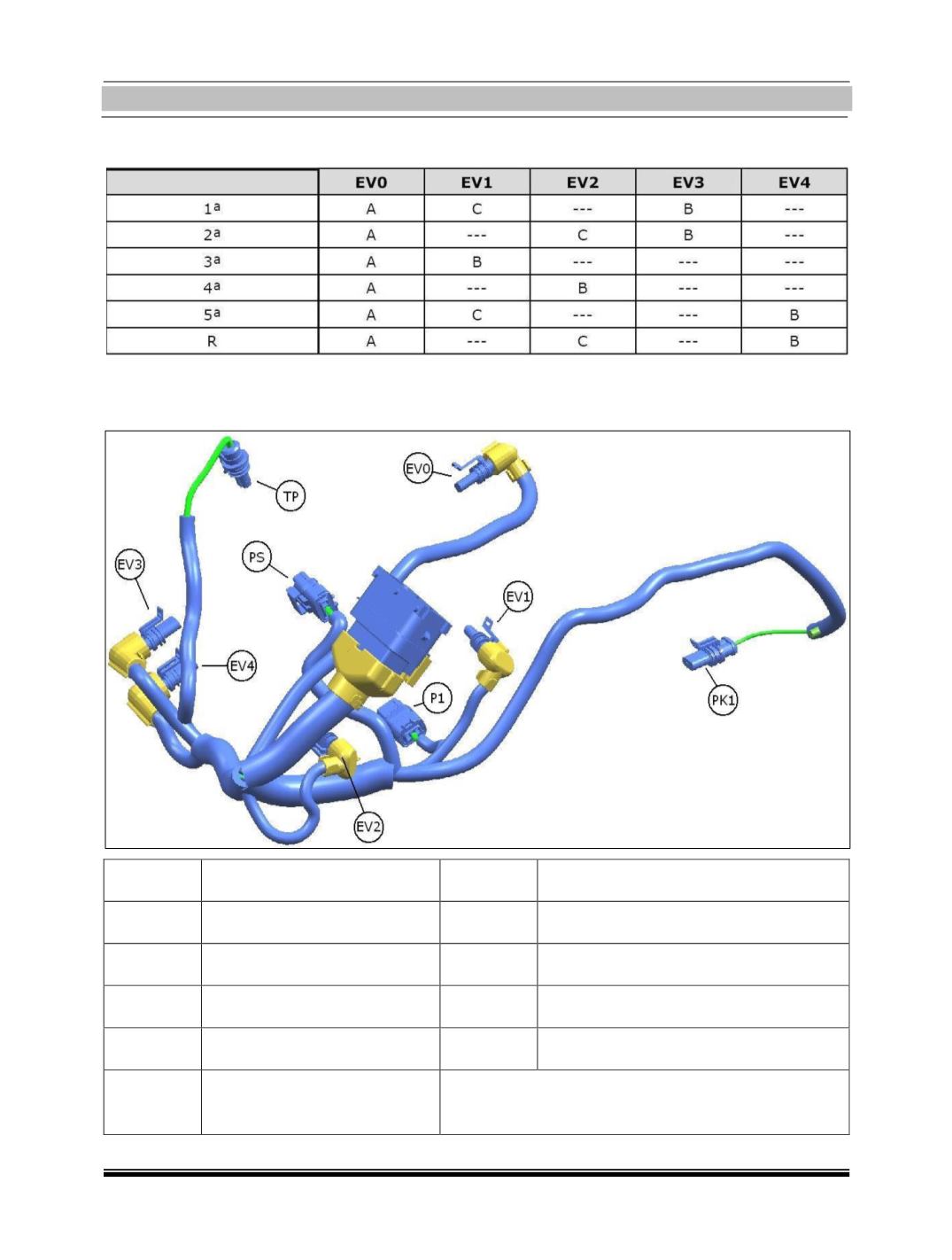
Electrical Wiring:
Connector
Function
Connector
Function
PK1
Main shaft rpm sensor
EV1
Odd gear engagement solenoid valve
P1
Engagement position sensor
EV2
Even gear engagement solenoid valve
PS
Selection position sensor
EV3
Position selection solenoid valve
TP
Oil pressure sensor
EV4
Position selection solenoid valve
EV0
Clutch operation solenoid
valve