


 502 / 1232

DRIVETRAIN C549
27
6. Remove the left differential internal driveshaft
(1a) using the tool comprising the brackets
(1b) 287458902603 (Brackets), the element
(1c) 287458902604 (Strut) and the mallet (1d)
287458902605 (Mallet).
7. Engage any gear using the gear selection
/engagement lever.
B. FIFTH GEAR - DISMANTLING
NOTE: In
case only the fifth gear assembly has
to be overhauled only removal of rear cover is
sufficient as shown in step no.4 of the
previous sub head
“
TRANSAXLE ASSEMBLY –DISMANTLING”
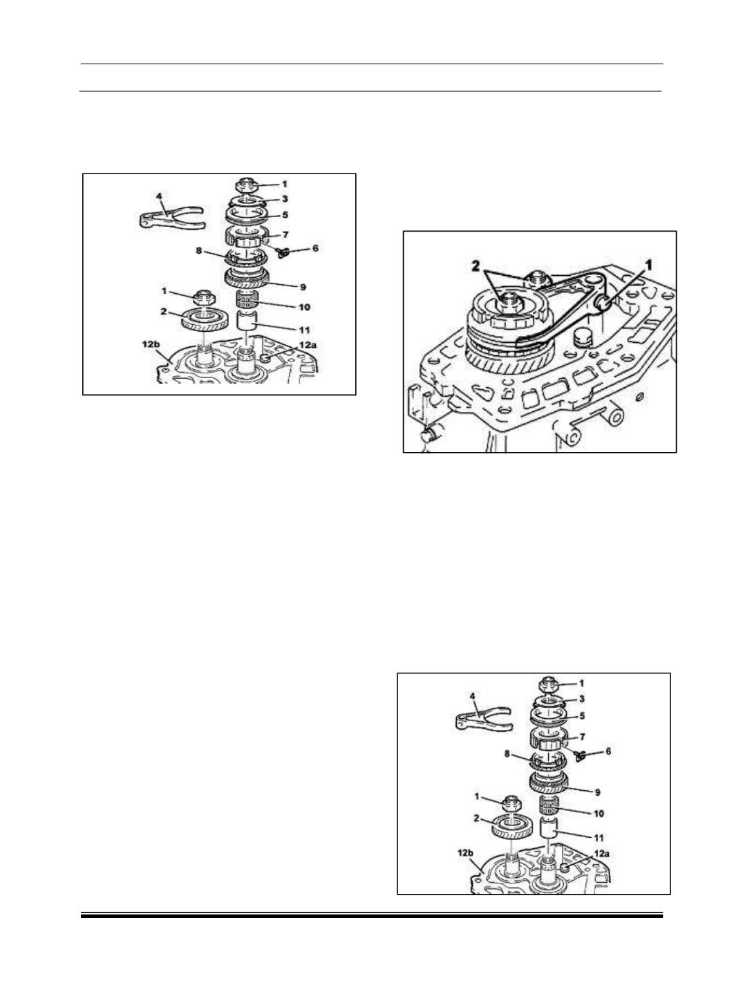
1. Unscrew the bolt (1) fixing the 5th speed fork
to the main shaft.
2. Engage 5th speed by pressing the fork on the
main shaft.
NOTE
If two gears are engaged simultaneously
the gear shafts will lock.
3. Remove the staking and loosen the ring nuts
for the main and lay shaft.
4. Place the 5th speed control fork in neutral.
NOTE: The positioning of the 5th speed
control fork in neutral is necessary to prevent
the synchronizer rollers from being lost.
5. Completely unscrew the ring nuts (1) for the
main and lay shaft.