


 984 / 1265

ELECTRICAL
80
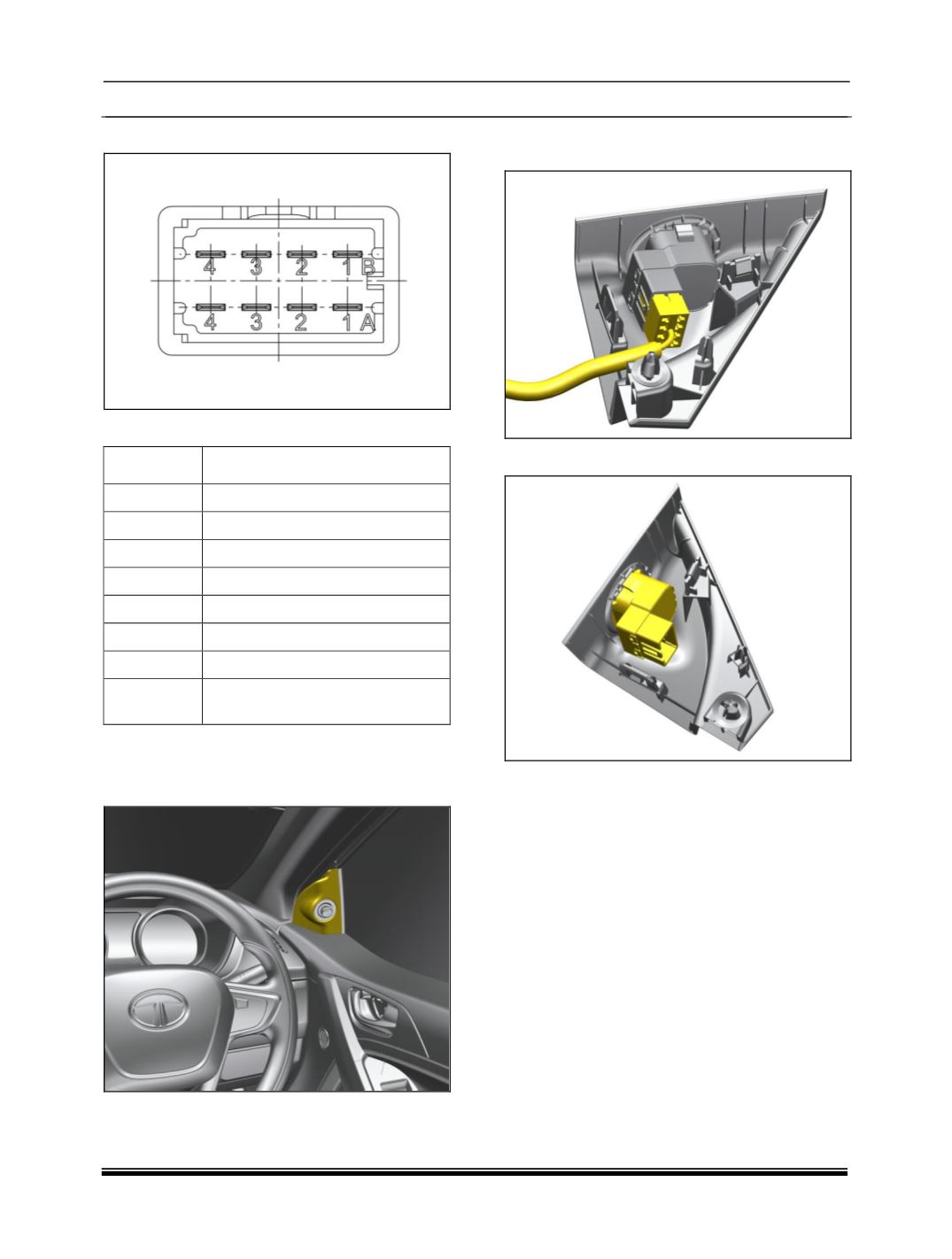
CONNECTOR DETAILS
PINOUT DETAIL
PIN
DESCRIPTION
1A
2A
ACC
3A
1B
2B
3B
GND
4B
4A
BCM INPUT (applicable for mirror
fold only)
REMOVAL
1.Pry out the Mirror adjustment switch cover from
cheater assembly.
2.Disconnect the electrical connection of mirror
adjustment switch.
3.Take out the mirror adjustment switch
.
REFITMENT
1.Connect the electrical connection of mirror
adjustment switch.
2.Fit the mirror adjustment switch
.(snap fitted)
.