


 857 / 1265

BODY
16
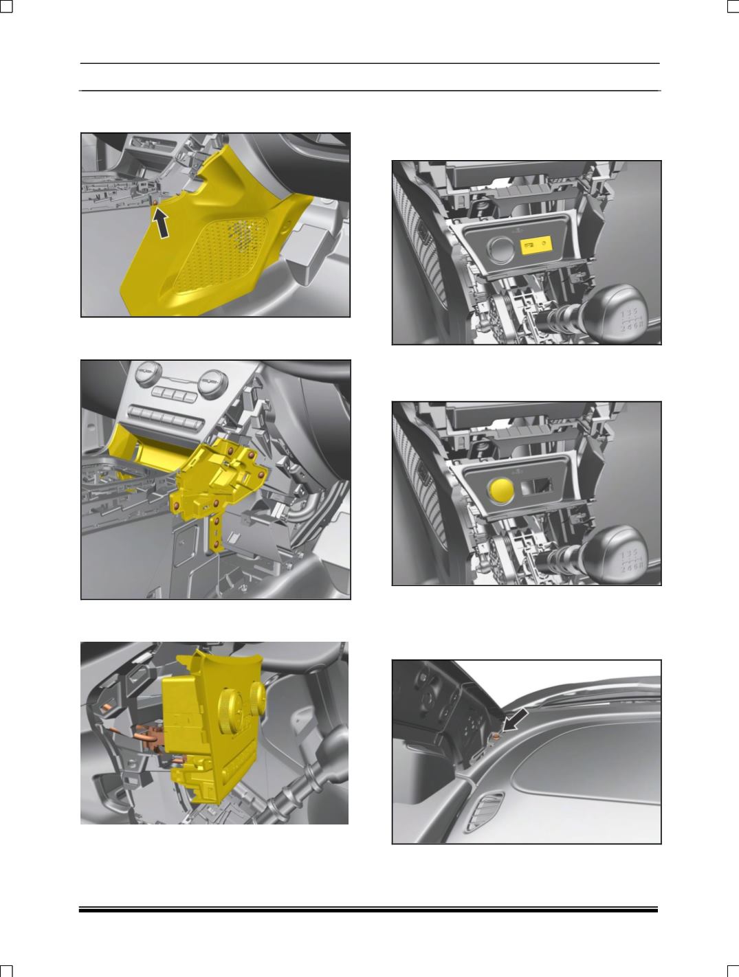
22. Remove LH, RH side mounting screw and pull
out panel.
23. Remove LH, RH side mounting screw of
console panel.
24. Disconnect two connections behind the
control panel assembly.
25. Disconnect USB auxin connectivity module
Assembly. (For removal refer USB auxin
connectivity module removal process in
Electrical section.)
26.Disconnect complete power socket assembly.
(For removal refer
power socket assembly
removal process in Electrical section.)
27. Remove A pillar Lower trim. (For procedure
refer A pillar trim removal process.)
28. Remove two mounting screw near A
pillar.(LH,RH)