


 721 / 1133

BODY
12
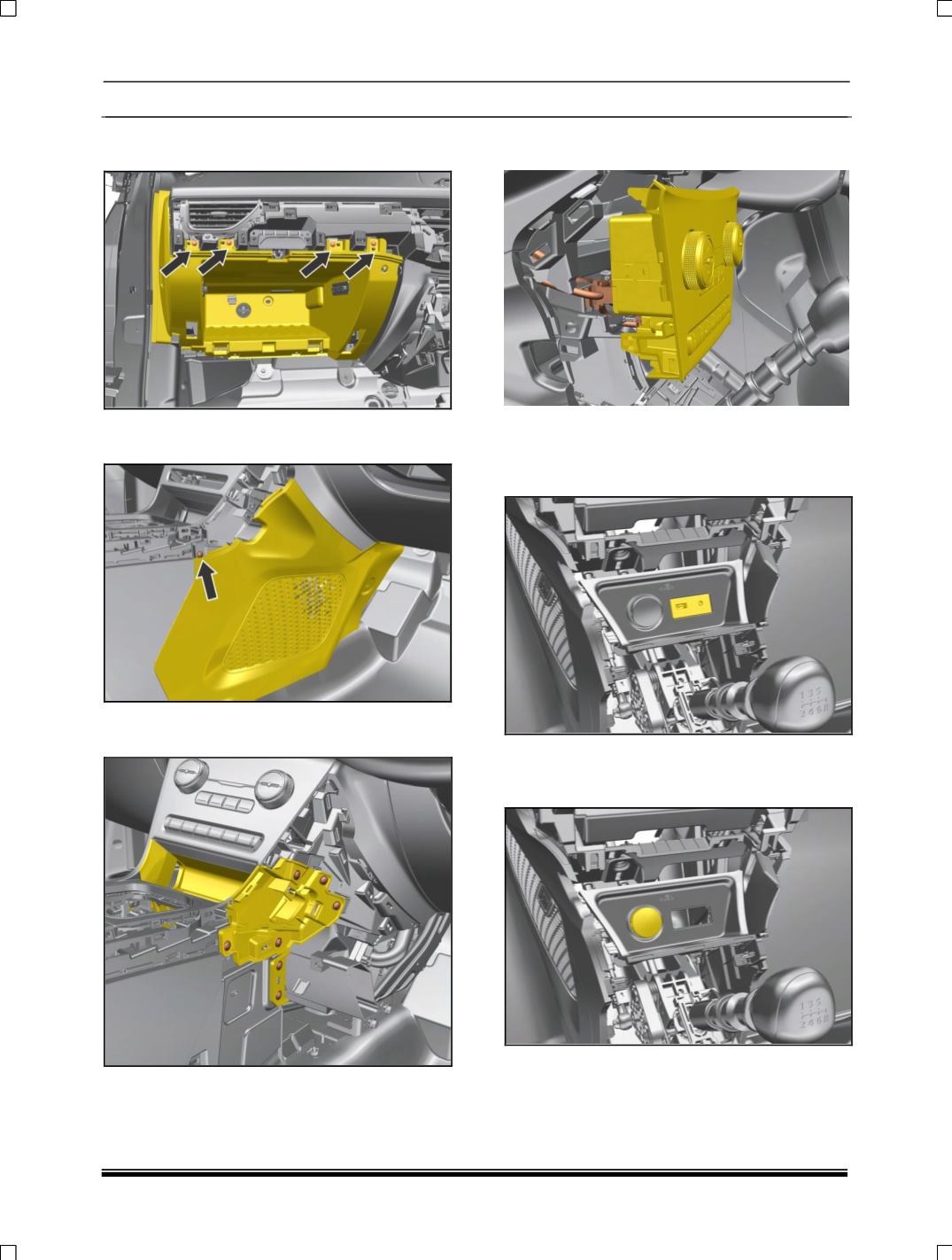
18. Remove four screw at glow box location and
pay out glow box
19. Remove LH, RH side mounting screw and pull
out panel.
20. Remove LH ,RH side mounting screw of
console panel
21. Disconnect two connections behind the
control panel assembly.
22. Disconnect USB auxin connectivity module
Assembly. (For removal refer USB auxin
connectivity module removal process in
Electrical section.)
23.Disconnect complete power socket assembly.
(For removal refer
power socket assembly
removal process in Electrical section.)