


 493 / 1133

CLUTCH
25
3. Check the rubber cover of pedal plate for
damage or wear.
4. Check the clutch pedal lateral play. (Before
Dismantling)
FITMENT
For fitment, follow reverse procedure of removal
.
NOTE
While assembling refer the stay rod assembly
procedure & caution.
NOTE
No clutch pedal play adjustment is required as this
vehicle is fitted with Hydraulic System.
At the time of assembly apply thin coat of grease
(Grease 3% MoS2, SS: 6820-320, TS:2520PI) on
clevis pin.
Align the axis of clutch pedal hole with the Clutch
master cylinder (CMC) fork hole and after
inserting the clevis pin through Clutch master
cylinder (CMC) fork and clutch pedal check the
free rotation of clevis pin.
While putting back the stay rod along with the
compression spring apply thin coat of grease
(Grease 3% MoS2, SS: 6820-320, TS:2520PI) at
the tip of the pivot pin in order to reduce friction.
Ensure the clutch pedal bush is fitted at the time
of assembly.
NEVER bleed the CSC if the clutch and flywheel
are not yet assembled.
Ensure that clutch switch adjustment is done after
fitment. (Refer clutch switch adjustment
procedure).
C. SELF ADJUSTING CLUTCH ASSEMBLY
REMOVAL
CAUTION
Do not clean the clutch disc with cleaning solvent.
1. Disconnect battery & electrical connections
of starter motor.
2. Remove the starter motor.
(For procedure
refer Electrical section.)
3. Drain the clutch fluid from the system. (Refer
Clutch Fluid Draining Procedure from this
section)
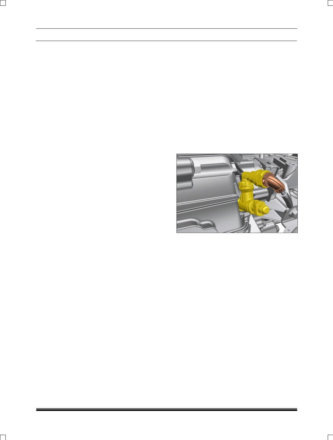
4.
Pull out the clip using a screw driver and
disconnect the high pressure line by pulling it
out.
5. Lower the gearbox from the vehicle. (For
procedure refer gearbox removal in Gearbox
section).
6. Insert the clutch mandrel into the centre of
the clutch cover and disc assembly and
unscrew the 6 mounting screws.
NOTE:
While unscrewing the clutch mounting bolts make
a practice of unscrewing the bolts evenly
(alternately crosswise) in small increments.
Remove the clutch cover assembly and the clutch
disc from the housing.
INSPECTION OF COMPONENTS:
1. Check SAC clutch disc hub splines for
damage and wear. The SAC disc set should
easily slide on the gearbox drive shaft but
should not have excessive play and wobble.
2. Check disc facing for wear, cracks, contact
pattern, burning marks and oil contamination.
Facings with any of the above defects or
worn out beyond permissible limits must be
replaced as a set.