


 742 / 1906

GEAR BOX
37
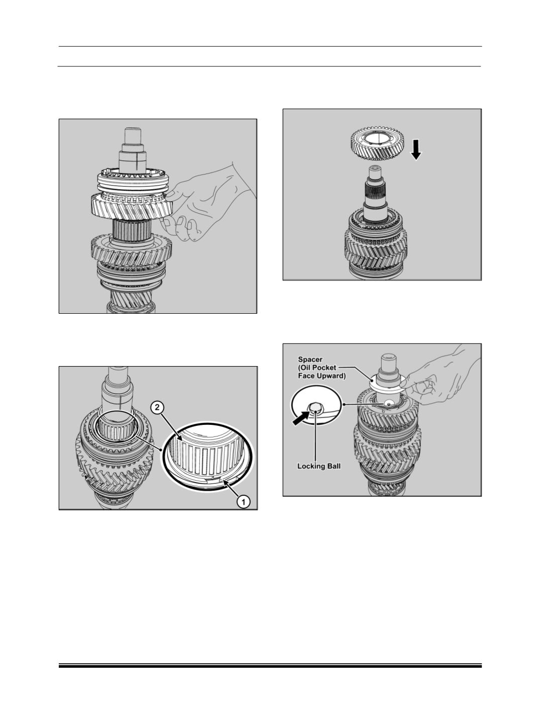
7. Insert the needle cage bearing. Slide the 1st
speed gear along with engaging gear on the
needle bearing such that the engaging gear is
upward.
8. Select suitable snap ring (1) and fit it over the
main shaft (Snap ring are available in the thick-
ness ranging from 1.7mm to 2.2mm in step of
0.05mm) and place the needle cage bearing (2)
9. Slide the 2
nd
gear sub-assembly over main shaft
along with synchro cone such that synchro cone
facing downwards.
10. Locate 3 mm Dia. locking ball at seat on main
shaft with help of grease. Slide spacer, aligning
notch with the locking ball. Ensure that oil pocket
over the spacer is facing upwards i.e. towards 3
rd
gear.
NOTE
The spacer has to be heated to 100°C to 120°C be-
fore assembly.