


 565 / 1906

ENGINE
133
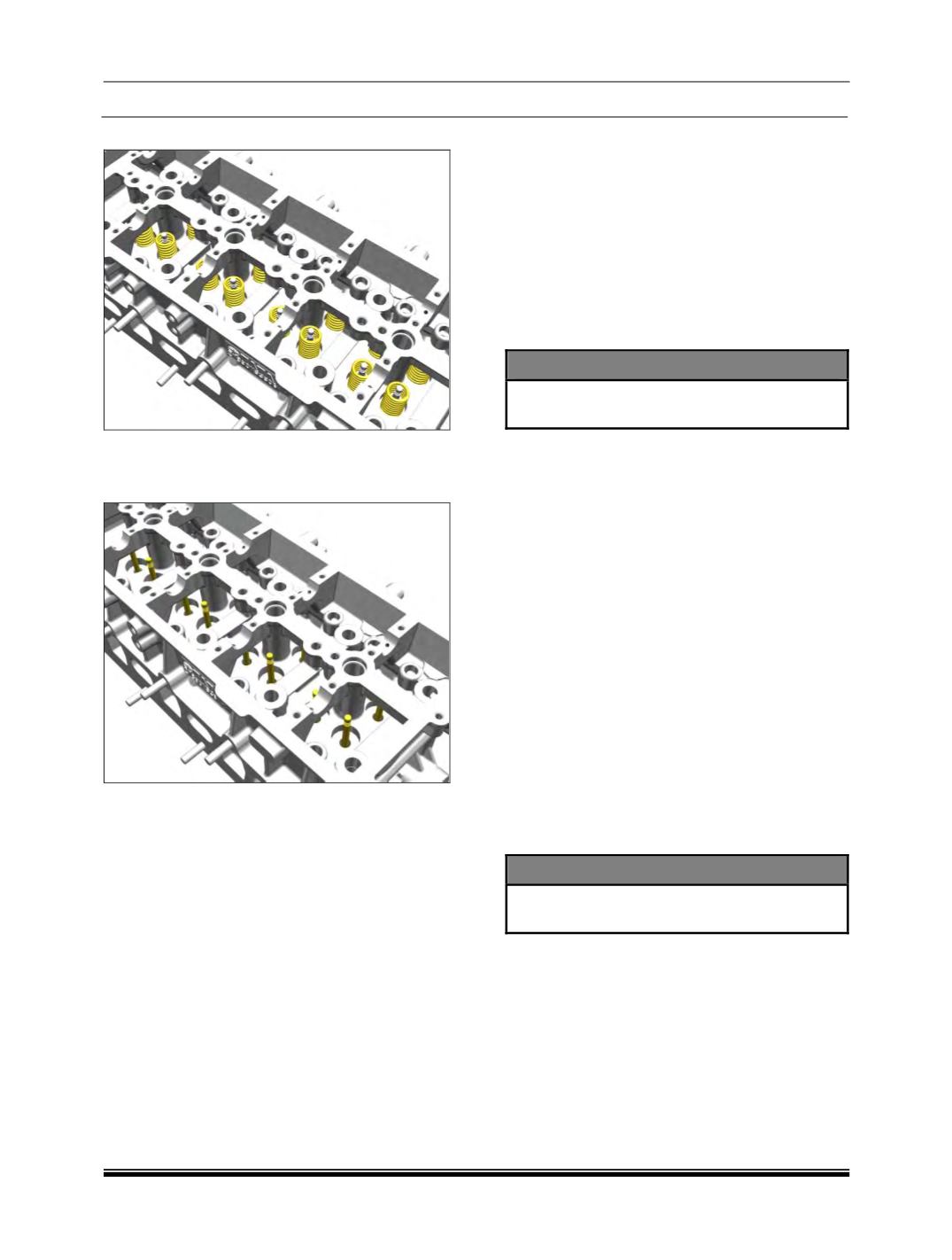
7. Remove the valve springs.
8. Remove the valve guide seals and take out
the spring seats.
9. Remove the valves. (Inlet and Exhaust)
10. Remove the cylinder head gasket.
INSPECTION :
A. Cylinder Head :
Checking Cylinder Head Mating Surface :
1. Using a straight edge and feeler gauge, check
evenness of cylinder head parting surface
with crank case. If unevenness exceeds
specified values, replace cylinder head.
2. Permissible unevenness of cylinder head
mating surface-0.030 mm
(Length wise).
3. Permissible unevenness of cylinder head
mating surface-0.015 mm
(Cross wise).
NOTE
Cylinder head top and bottom surface re-
machining in service is not permitted.
B. Valves :
1. Check valve leakages by pouring gasoline on
valve head. Gasoline must not seep past
valve seat.
2. Valves with burnt heads, excessive scoring
and wear on stem should be replaced.
3. Check valve seat run out with respect to valve
stem. If it exceeds specified limit replace
valve. No attempt should be made to
straighten bent valves.
4. If valve is free from any other defects except
worn out seat, then only it can be re-matched
on valve grinding machine as follows:
Clamp valve on grinding machine jaws as
close as possible to valve head.
Adjust grinding angle on graduated scale to
achieve correct valve seat angle.
Feed valve slowly towards grinding wheel
until wheel just touches valve head.
Grind at low feed until valve seat is just
clean all around.
NOTE
After grinding valve head thickness should
not be less than 0.85 mm.
C. Valve Guides :
1. In case of valve stem sticking in valve guide
bore or Excessive clearance between them,
remove valve guide From cylinder head using
drift (Part No.2868 5890 06 05).
2. Check the condition of valve guide oil seals.
3. Check valve guide bore diameter in cylinder
head and if necessary, ream valve guide bore
in cylinder head to next over size.
4. Install matching size valve guide in cylinder
head using drift (Part No. 2868 5890 06 05)
and spacer (Part No. 2653 5890 06 01).