


 570 / 1906

ENGINE
138
then be finished on a connecting rod boring
machine.
16. Ensure that the connecting rod big end and
small end axis are parallel to each other
within the specified limits. Centre to center
distance between connecting rod small end
and big end is maintained within specified
limits.
17. If one or more connecting rods are to be
replaced, ensure that difference in weight of
connecting rod in one engine is within
permissible limits.
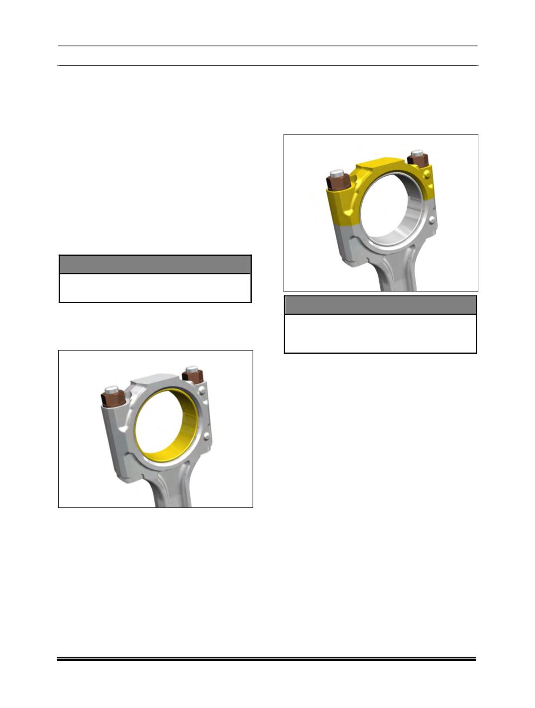
18. Install new pair of connecting rod bearing
shell according to size of crank pin journal
diameter, making sure that securing lugs of
bearing shells are properly seated in grooves
of connecting rod and its bearing cap.
NOTE
Lower and upper bearings are not
interchangeable.
19. Install connecting rod bearing cap with
bearing shell on connecting rod. Tighten
connecting rod bearing cap mtg. nuts to
specified torque.
20. Measure connecting rod bearing bore. Record
the readings in the format given in this
manual.
21. If connecting rod big end parent bore
dimension is maintained within specified
limits, proper bearing bore dimension is
automatically achieved.
22. However, it must be physically measured and
confirmed. Measure pretension of connecting
rod bearing shell with a feeler gauge after
loosening connecting rod bearing cap
mounting nut on opposite side of bearing shell
lug.
NOTE
Connecting rod bearing shells are precision
finished and should not be bored or
scraped.