


 1895 / 1906

HVAC
81
B. CONTROLS
PUSH BUTTONS
1. AI(
Air Inlet
) Control request (
Amber LED
):
The AI pushbutton shall be of non-latching type and
located on top of the hollow knob used to select the
blower speed. The AI door flap shall be controlled
either manually by the user pressing the AI control
button on the panel or automatically by the climate
control algorithm.
MANUAL OPERATION
:
As a manually selected two state function, the air
inlet door flap will be either outside air (
OSA
) or in-
cabin recirculation (
RECIRC
). The default position
shall be outside air (
OSA
). When the user pushes
the AI control request button, the air inlet door flap
shall move to the RECIRC position and the LED
shall turn on. The next time the user pushes the RE-
CIRC request button, the air inlet door flap shall
move to the OSA position and the RECIRC LED
shall turn off.
AUTO OPERATION
:
The AI
(AIR INTAKE)
control shall switch to Auto
operation immediately after the user presses the Au-
to request button. The status of the AI door flap shall
be calculated by the Climate control algorithm. Dur-
ing Auto operation, it shall be possible to stop the AI
door flap at intermediate positions between Recircu-
lation and OSA as required by the algorithm. The
LED shall not indicate the status of AI door flap dur-
ing Auto operation.
2. Normal A/C request (
Amber LED
)
The A/C request button shall be of non-latching type
and located on top of the hollow knob used to select
the cabin set temperature. Using this button, the user
shall be able to choose between Normal A/C and
A/C off state
.
3. Auto control request
By pressing the non-latching Auto request pushbut-
ton, the user shall be able to activate fully automatic
temperature control.
4. Rear defog request
The rear defog pushbutton shall be of non-latching
type and used to manually switch ON/OFF the rear
defog heater grids on the rear window. Enabling the
heater, allows the clearing/defogging of the rear win-
dow.
After ignition ON, the default value of the rear defog-
ger shall be OFF. The rear defogger shall be
activated by pressing the pushbutton on the control
panel during engine ON condition. The status of the
Rear defog shall be indicated on the display. If the
Rear defog switch is activated in any ignition cycle, it
shall remain on for a calibratible amount of time (
ap-
prox. 15 minutes
).
5. Front defrost request
The Front Defrost Request pushbutton shall be of
non-latching type and used to manually switch the air
distribution to defrost mode. This shall be used for
clearing/defogging the front windshield. The Air inlet
and the temperature door flaps shall be selected au-
tomatically to aid the window clearing operation.
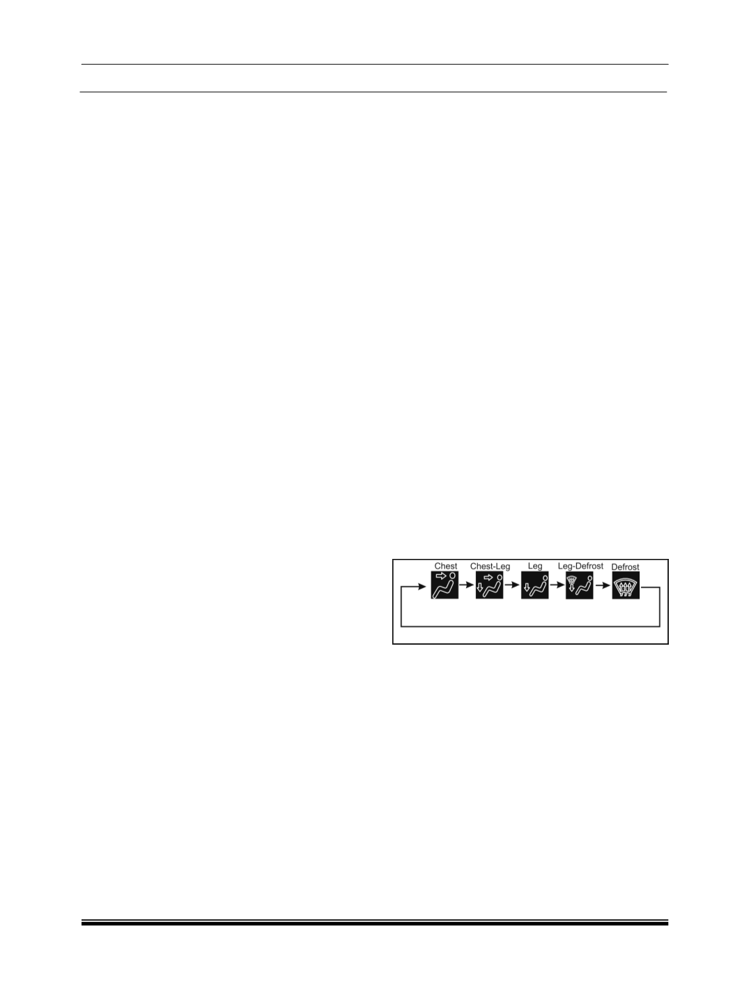
6. Mode (
Air distribution
) selection button
The Mode selection pushbutton shall be of non-
latching type and used to manually select the air dis-
tribution modes. It shall be possible to manually
select the various distribution modes in a cyclic fash-
ion, for every push of the button.
The Mode control shall be functional at all times
when the control head receives the ignition voltage.
Mode control shall indicate the control of the air dis-
tribution inside the cabin. The Mode control shall
happen either manually or through an automatic cli-
mate control algorithm. The determination of the
desired mode position shall be described by the sim-
ple flow diagram below.
Mode control during Auto operation
The Mode control shall switch to Auto operation after
the user presses the Auto button. The desired mode
position shall be determined by the climate control
algorithm during Auto operation. The Auto operation
shall select among Chest, Chest-Leg and Leg posi-
tions during the Auto operation. Since the system
isn’t equipped with sensors to determine the wind-
shield fogging criteria, the Defog and Defrost shall be
selectable manually by the user. The display of the
mode-man icon shall remain blank and not indicate
the current mode during Auto operation.